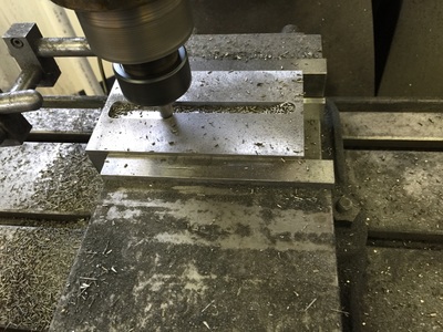
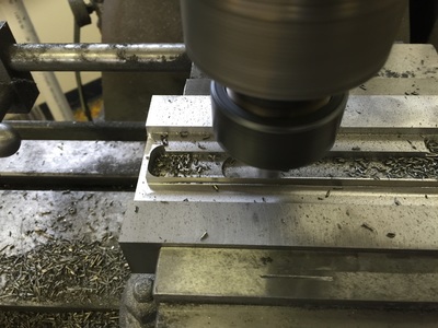
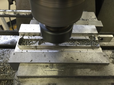
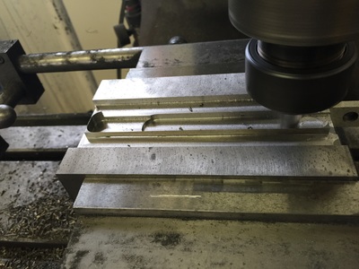
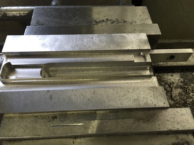
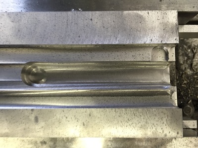
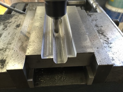
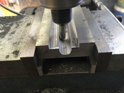
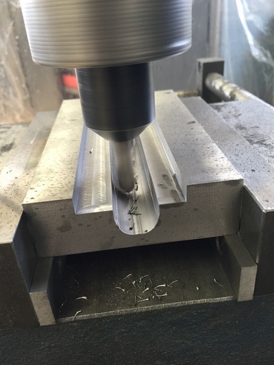
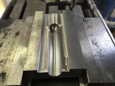
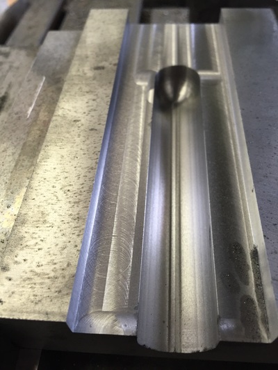
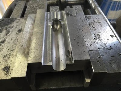
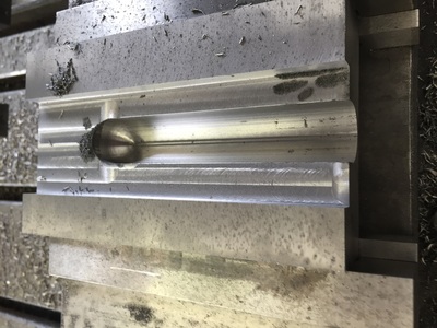
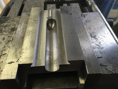
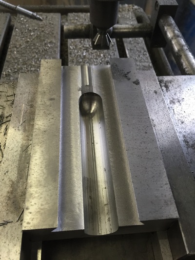
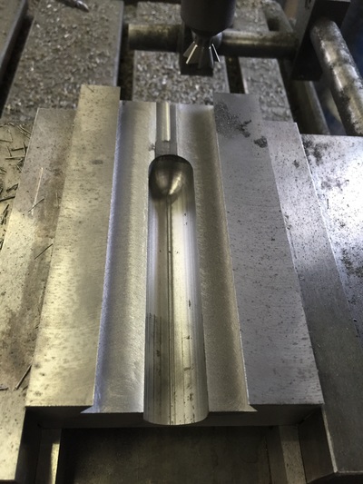
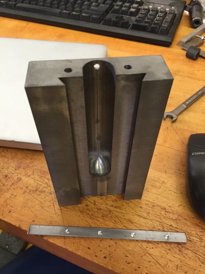
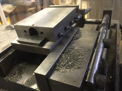
High on my success with the cross slide casting, I decided to pursue a replacement compound rest project. The stock 10" Atlas compound rest is flimsy and has limited travel. I designed it when I should have been doing other things like paying attention in law school classes. The goal for the design was to allow machining of an MT3 taper without a taper attachment. This required an extension of travel, but I didn't want to unduly increase the compound's size to avoid compromising capacity or usability. I also wanted it to be able to use original parts so that I didn't have to make everything from scratch. If anyone is interested, I could generate drawings of the parts. Obviously some adjustment and fitting may be required because I had a few minor revisions based on machining variances. CNC was useful for machining the screw channel in the underside of the top slide, but it could probably be done with a very large ball-mill.
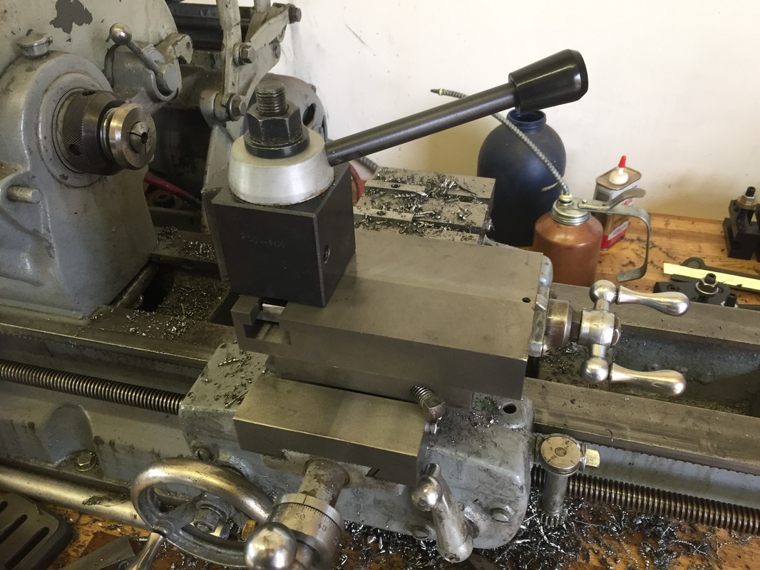
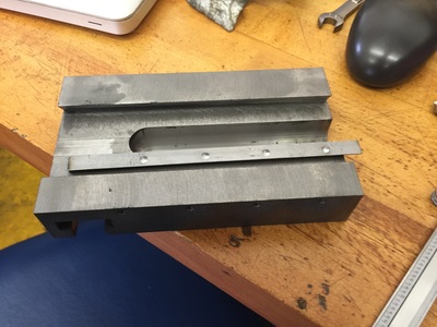
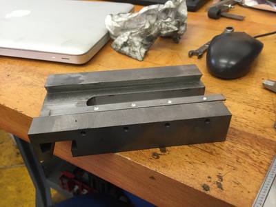
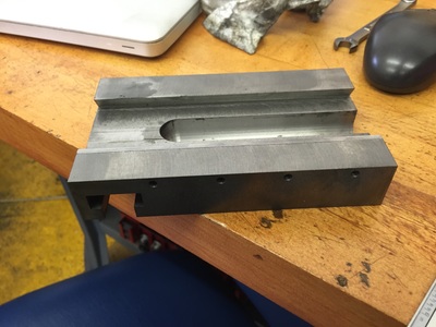
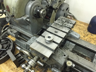
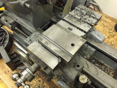
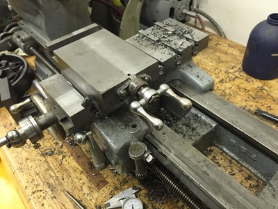
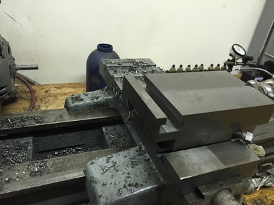
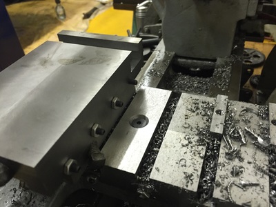
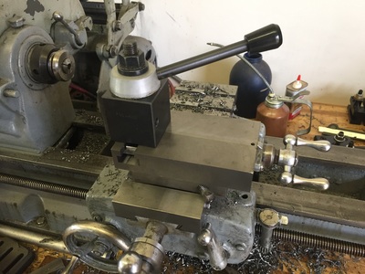
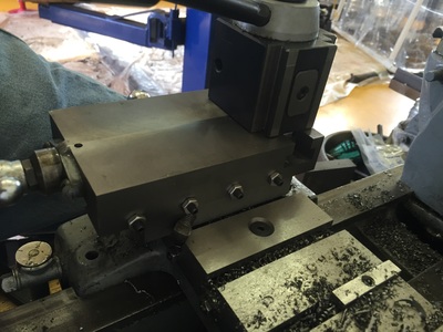
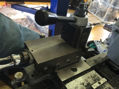
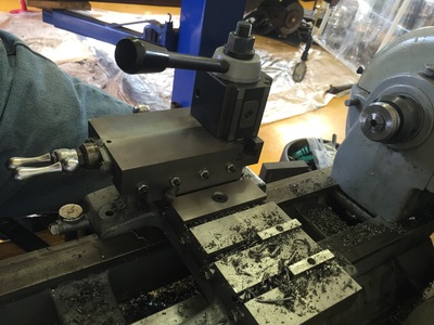
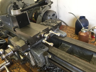
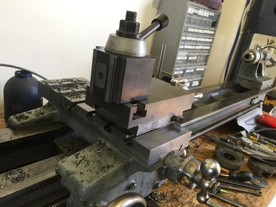
As you can see, it's a much "squarer" design than the original. But it uses the original compound nut and screw assembly. It sits slightly higher than the stock compound, so the tool holders need to be adjusted accordingly. But the tools still land well within the range, even with the added heigh of the cross slide and compound rest.
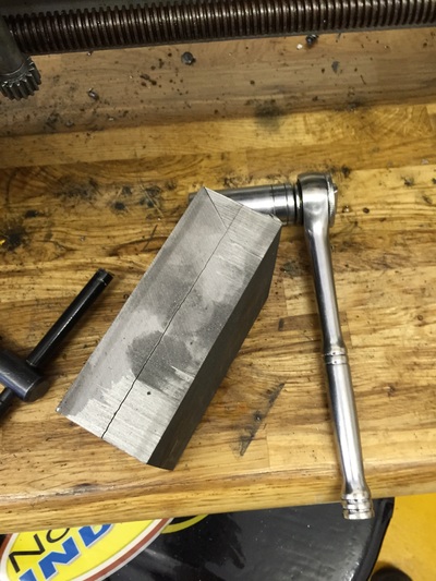
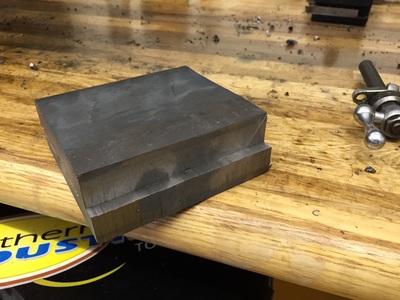
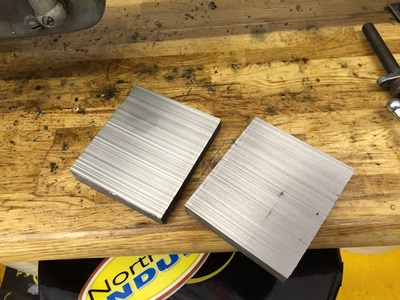
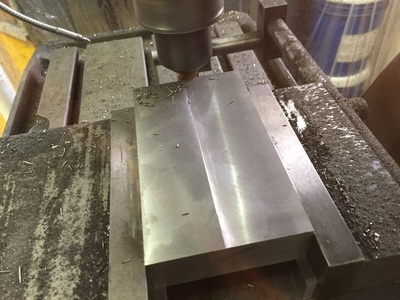
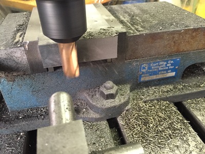
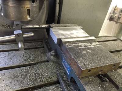
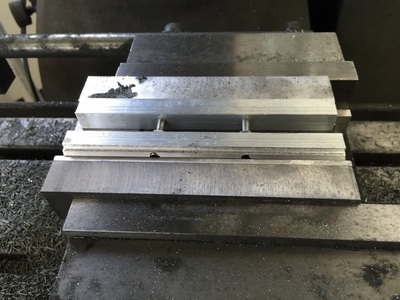
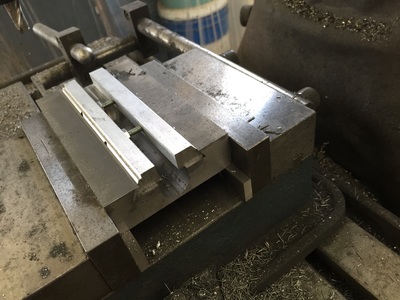
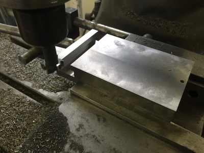
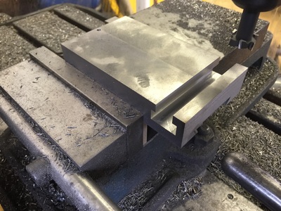
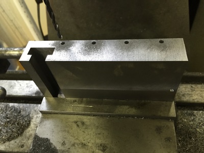
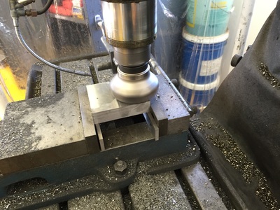
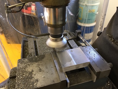
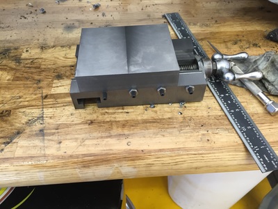
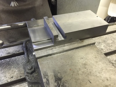
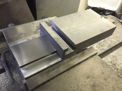
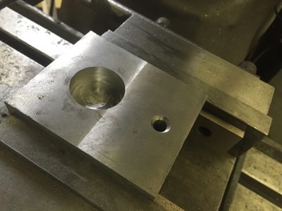
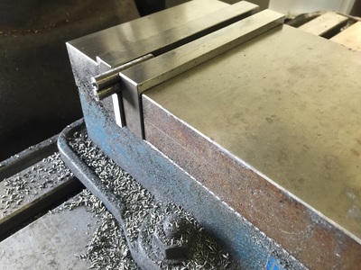
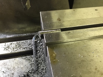
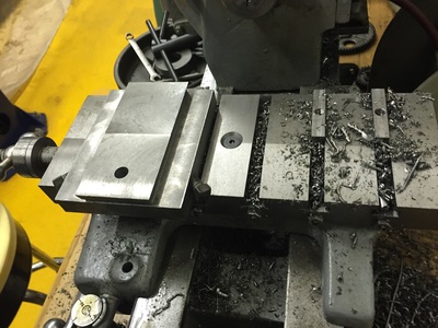
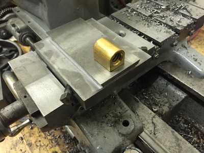
I started out with a chunk of continuously cast iron bar and sawed it in half along the thickness. I had enough machining margin to do this by hand on the bandsaw. Then decked the blocks to size with that trusty face mill. My initial calculations on the size of the screw clearance groove were a bit off, so I had to enlarge it after I already started. I'd rather the center had a bit more thickness. I'm thrilled with the results thus far, but to realize maximum travel I have to make a new screw. I bought the necessary precision rolled Acme screw, but haven't yet attempted it.
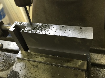
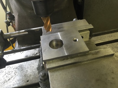
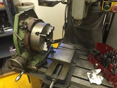
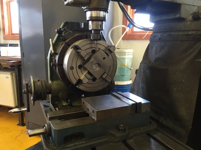
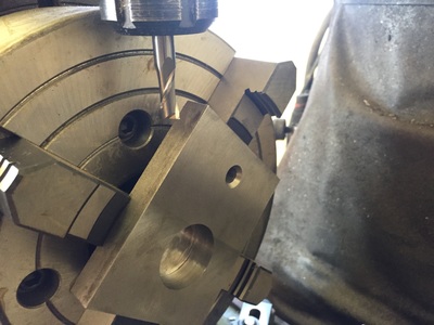
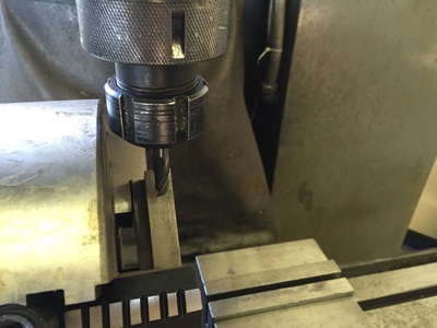
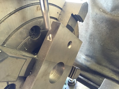
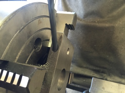
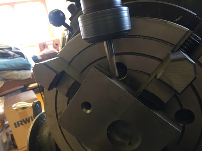
Another step of note is the drilling of the clamping screws at 45 degree angles from the part centerline. I set up the rotary table on the mill. It's a 12" diameter table, and I fitted a 10" 4 jaw chuck. Once I got it centered up, I had to make sure that I could get the machining operations done without hitting the spindle to the chuck. It was a bit dodgy, but it worked. And having CNC made it easy to repeat the other side once I got it positioned.





 RSS Feed
