It's time to get cracking! I received the bulk of my parts before I began the teardown, so that I could get a feel for how big they actually were. Compared to the original equipment, not very!
First off, let me explain my philosophy. I didn't feel like doing a lot of complicated modifications. It is ENTIRELY possible to remove either the control or power cabinet in its entirety, so long as you have a mains disconnect switch within view of the machine (per code, at least in the US). I chose to keep the PC outside of the machine, but it could also easily be situated inside the machine. Finally, I chose to power the entire machine, aside from the PC, from my single phase 240V circuit, rather than use multiple circuits. I recommend this approach due to the improved safety benefits. One disconnect removes ALL power to the entire machine so there is no chance of electrocuting yourself whenever the switch is off.
First off, let me explain my philosophy. I didn't feel like doing a lot of complicated modifications. It is ENTIRELY possible to remove either the control or power cabinet in its entirety, so long as you have a mains disconnect switch within view of the machine (per code, at least in the US). I chose to keep the PC outside of the machine, but it could also easily be situated inside the machine. Finally, I chose to power the entire machine, aside from the PC, from my single phase 240V circuit, rather than use multiple circuits. I recommend this approach due to the improved safety benefits. One disconnect removes ALL power to the entire machine so there is no chance of electrocuting yourself whenever the switch is off.
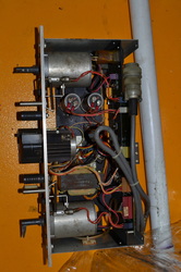
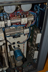
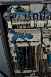
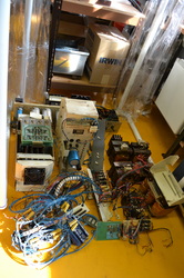
Disclaimer: This may not be the most efficient way. In fact, I'm sure it's not. But it worked for me and I didn't damage any of the old parts in the process. See below for all photos of the teardown.
Step 1: Clean up around the machine so you aren't fighting with junk as you work on the machine! You don't want chips in your pants either!
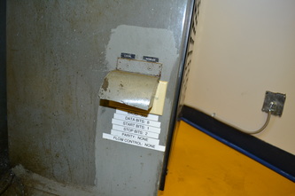
Unplug the RS-232 cable from machine (if you have one connected)
Switch the breaker off. Electricity hurts.
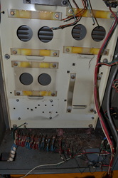
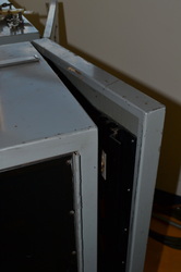
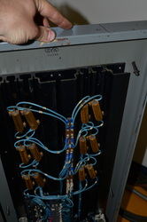
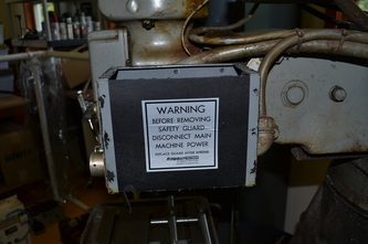
Remove the control cabinet cover panel and open the power cabinet door with a flat bladed screwdriver.
Disconnect machine power by pulling L1, L2, and L3 wires from the outside of the machine. These should be your three phase power into the machine. Move them out of the way, you'll probably want to reuse the wires later (rewired for single phase, of course).
Get out your maintenance manual and check the schematics - don't want to unwire something before you understand where the wires go! However, in retrospect, that's not such a big deal. It's not too difficult to probe the components to figure out what you need to connect so don't stress if you can't remember out which wire is which.
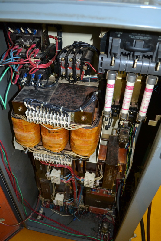
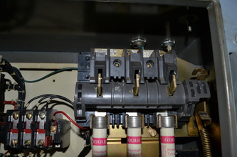
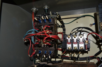
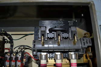
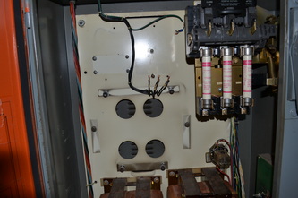
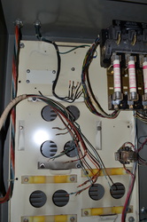
Remove the wiring from the master power disconnect switch (top right). Initially I tried to preserve it but forgot that it runs directly to the motor contactors (relays to us non-electricians), then to the motor overload relay. Incidentally, I believe that the overload relay was a good idea, but when I wired my breaker for 240V Single phase, 30A, it would always kick the breaker if the spindle did not start properly, rather than trigger the overload relay. Last time I checked, 30A at 240V is less than 1800VA that the relay is supposed to overload at. I question whether it really works for 'normal' overloads.
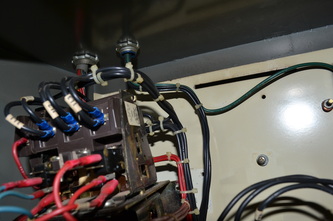
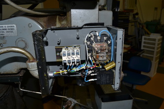
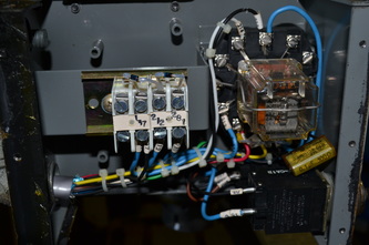
Remove the motor overload relay and motor contactors. This will require a #2 philips screwdriver. One of the four motor overload relay mounting screws (bottom left) is difficult to reach. With care, you can angle the screwdriver and turn carefully to get it to move without stripping. It only needs to be loosened, then you can lift the relay assembly up and it will slide off the slot in the mounting bracket.
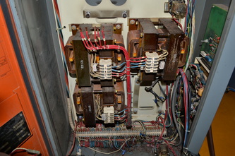
A small pair of nippers may be useful to cut the zip ties. In my effort to avoid just randomly unhooking everything, I'm avoiding the 24VDC wiring until I get a better look at it. In order to get the motor contactor wiring out without just unwiring every one of the dozen plus connections, I traced it down to transformer T1.
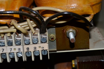
It wouldn't hurt to unhook the L1, L2, and L3 wiring from Transformer T2, just under the motor overload relay.
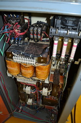
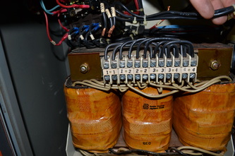
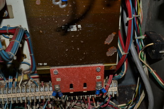
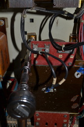
Unhook the connections on T1, then get your socket set. Unbolt T1 from the cabinet. You'll need a 7/16" socket and a long extension so that you can do it comfortably. Judging by the looks of the other bolts, they're all 7/16" but we'll see.
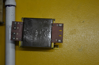
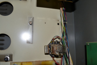
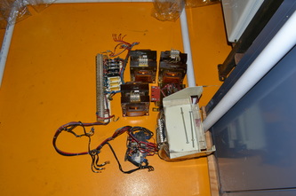
Victory! T1 is removed. Careful, though, as it weighs a ton. There's a support under each transformer, so it won't fall until you remove the last bolt. Then it will fall outward toward you. I dropped it, but it didn't damage anything. T2 is quite a bit bigger, so I expect I'll have to be prepared for that one!
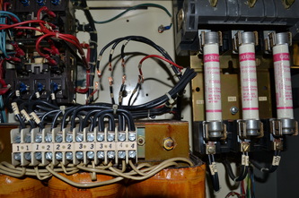
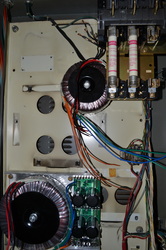
Ok, the wiring from the motor relays goes down the right side of the cabinet, under T1, and then along the top of the terminal strip. This is not going to be easy to do tidily. Let's just get rid of T2. It has a retaining bracket that is held on by socket head cap screws. Get out your 1/4" allen wrench! Allen sockets make this job easy.
Now what's holding it in? It should slide right out. Get a spanner or deep well socket and take these nuts off on the bottom side of T2. The stud is just a length of threaded rod, so there's a nut at the back. I didn't need to hold mine, they stayed in place by themselves, but you may have to secure them at the back with another wrench. It shouldn't be impossible to get a spanner back there. Once that was done, I struggled with why it wouldn't come out. It may be bonded to the back plate by heat and age. Use your socket extension to pry it loose. Now gently slide it forward on the lower bracket, and carefully lift it out of there. It must weigh 60 pounds, so be careful. Carry it away!
Now remove the SX1, SX2, and SX3 transformers. Fairly straightforward.
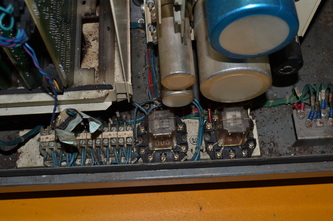
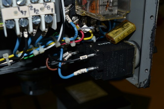
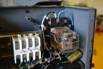
Now, I removed the 120V relay at the bottom to make room, but will probably end up reusing it later. Note: no, I didn't. But relays are always good to have.
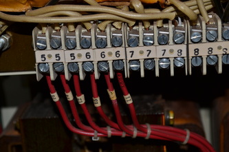
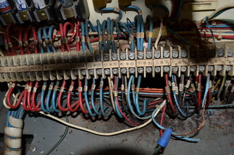
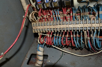
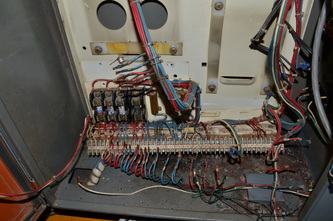
Disconnect the wiring from the control cabinet at the terminal block, making sure to remove the ground underneath the terminal block, at the bottom left. Remove other wires as necessary.
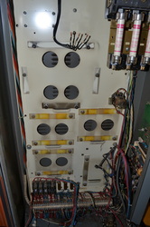
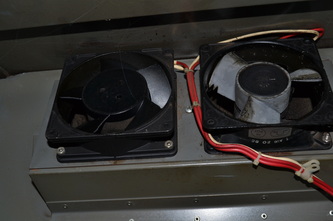
Remove the 5 philips head screws and remove the fuse, power resistor, and terminal block panel from the back plate. I just disconnected the fan at the plug because it was difficult to unbundle the power wire from the rest of the terminal strip wiring.
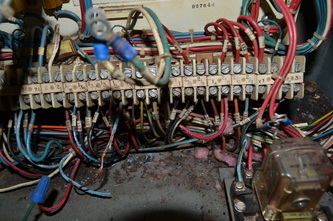
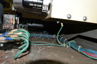
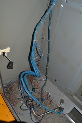
At this point, I vacuumed. It wasn't too tidy in the bottom! I would recommend washing your hands before going to eat something. There was, at one time, a mouse nest in the bottom of the power cabinet. There's some evidence of chewed wires, but the machine still worked! I plan to reuse most of the wiring to the external devices as long as it doesn't have cracks or damage. Note: the peripheral wiring was actually reused. Wiring to the steppers, limit switches, etc, was left in place because it was in good condition. Your mileage may vary.
Interestingly, there's an hour meter on my machine. Who knew? It reads 8500 hours, which is amazing considering I'm the third owner. That's just over 4 years of operation, assuming only 1 shift! Hard to believe. Bendix originally purchased the machine, so apparently the previous owner (who worked at the local Bendix plant) was correct when he told me that once they got the Boss 6's, they only used this one occasionally. I can't imagine how it could have so little use otherwise. Of course the hour meter could have malfunctioned, but the ways are awfully shiny.
Wish my VFD was here, I could have it mounted up and wired to the spindle motor in no time!
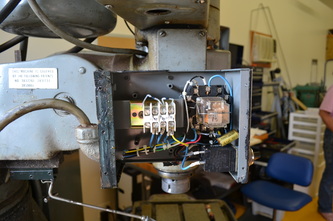
I am using the schematics to sort out the wiring for the spindle brake panel, the spindle motor panel, the bijur lube pump, the coolant mister, and the spindle brake solenoids. Wherever the wire labels have fallen off or aren't clear, I will have to resort to using my meter. Let's see, what next?
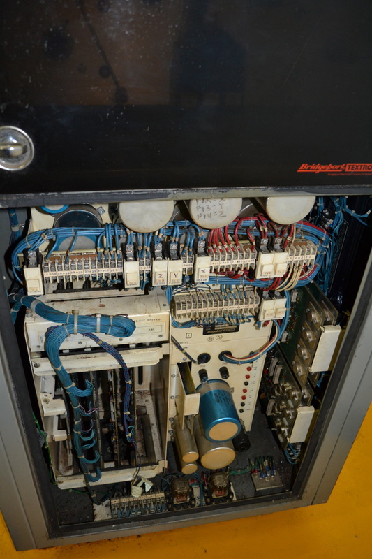
Time to start on the control cabinet while I consider how many terminals I need for my terminal strip. Certainly not as many as Bridgeport!
First, remove the tape reader by removing the socket head cap screws securing it. These require a 5/32" allen wrench.
Once you remove the 4 screws on the thick aluminum panel, the tape reader will be loose.
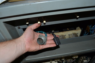
Pull it out, disconnecting the Mil style connector by unscrewing the large knurled ring all the way, then pulling it apart. Then remove the 115V plug from the back.
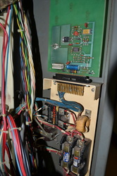
I attempted to remove the DC power supply first ... this was a bust. It won't fit without first removing the large supply above it with the large terminal strip.
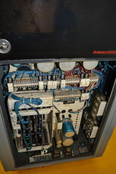
Open the door at the side of the control cabinet for better access. Remove the stepper motor driver boards and the ACC board. This makes more room to work.
Looking at the terminal strip on the DC power supply, unhook every single wire from the wiring bundle that comes from the power cabinet so that the two power supply boxes are free of obstructions.
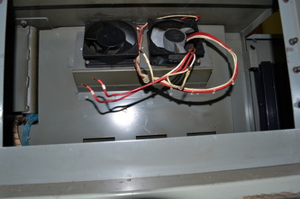
Remove the 115V receptacle that the tape reader power cable plugged into. This requires unbundling the 115V (red) and neutral white wires for the fans at the top. I plan on using them in the final version, so I don't want to destroy the wiring.
Gently remove the top power supply once the socket cap screws are removed.
Do the same with the lower power supply.
Make sure that the wires to the LSI-11 & other control boards are removed, then remove that cabinet, boards and all. There will be one ground wire coming from the bottom of the card cabinet. It will require that you clip all the zip ties to the ground panel in the front right corner. Use a philips screwdriver, and hold the nut on the bottom with a finger. It should come out easily.
I got the TRS30R fuses I needed for the mains disconnect switch in the power cabinet at the electrical supply. They had them in stock at about $14 each with tax. You may be wondering why I used two. Frankly, rather than engineer a bar that would replace the second fuse for single phase power, I simply used two 30A fuses. The factory fuses are only 20A and that most likely will not be enough to drive steppers and the spindle at a reasonable load. I fitted the fuses, they're quite difficult to remove, so be careful to avoid gashing yourself.
I still have to remove the auxiliary boards (that supply power to the worklight and coolant system), mount the terminal strip, and mount the VFD before I can begin wiring the power cabinet. In the control cabinet, I just have to separate the wiring from the limit switches from the control panel wiring and the rest of the wiring harness. I'm going to leave the control panel wiring in place for now, but ultimately I plan on retrofitting a setup to do manual controls. My PC will remain at the bench next to the machine, so it will be convenient to manually jog it up close and personal. Maybe someday I'll fit the machine into the control cabinet. There sure is plenty of room. It occurred to me that if you remove only the stepper drive boards & extraneous terminal strips, etc, it would be possible to install the drivers on the large heatsink and leave everything else in place. For the 'labor efficient' conversion! Of course, I never seem to do things the easy way.
Go ahead and remove the wiring harness and misc. other items.
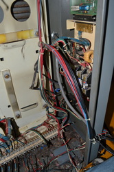
In the control cabinet, just unclip the zip ties until you've got the pendant's wiring and the limit switch wiring freed from the rest of the harness. Ultimately, only the wiring on the heat sink will remain.
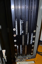
On the heat sink, I just removed all the socket head cap screws from the top down, then got a 1/4" socket to remove the board mounting brackets. Then use a 7/16" socket to remove all the diodes in the heat sink. Finally, I undid the wiring harness from the terminal strip at the bottom and unscrewed the terminal strip. You'll have to get behind it with a 5/32" wrench and it can be quite a pain. Then drop the panel, remove all the wiring (it should come right out).
I replaced the terminal strip panel as I may use it later. All of the stepper wiring is still connected to it at this point. Now I'm ready to vacuum up. It's getting quite messy on the floor.
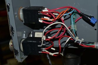
Remove the SCA boards (this could have been done much earlier). This requires unwiring the coolant and lighting receptacles. Later I will rewire them and connected them to 120V. The coolant will have power supplied through a solid state relay, so I'll need one of those.
Took the fan connector & associated wire from the old fuse holder. Later I will wire it into 120V power. It will work perfectly without any extensions.
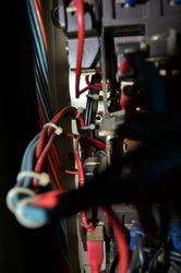
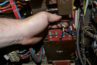
That's basically it. I didn't detail every step of the teardown, but you get the picture. The key details of re-wiring & reassembly are in the next section, so don't worry if you didn't write everything down.
 RSS Feed
