The next step is what we've all been waiting for ... putting it back together! Read on for a blow by blow of my adventures. This section includes key information like what to connect where, etc. I'll draw up a wiring diagram and publish my configuration files at the end, but for now, this is most of what you need to get cracking.
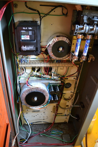
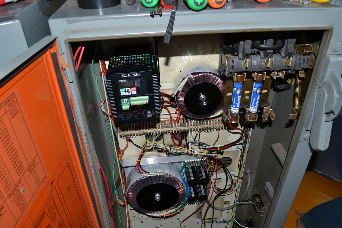
Power Cabinet ... completed!
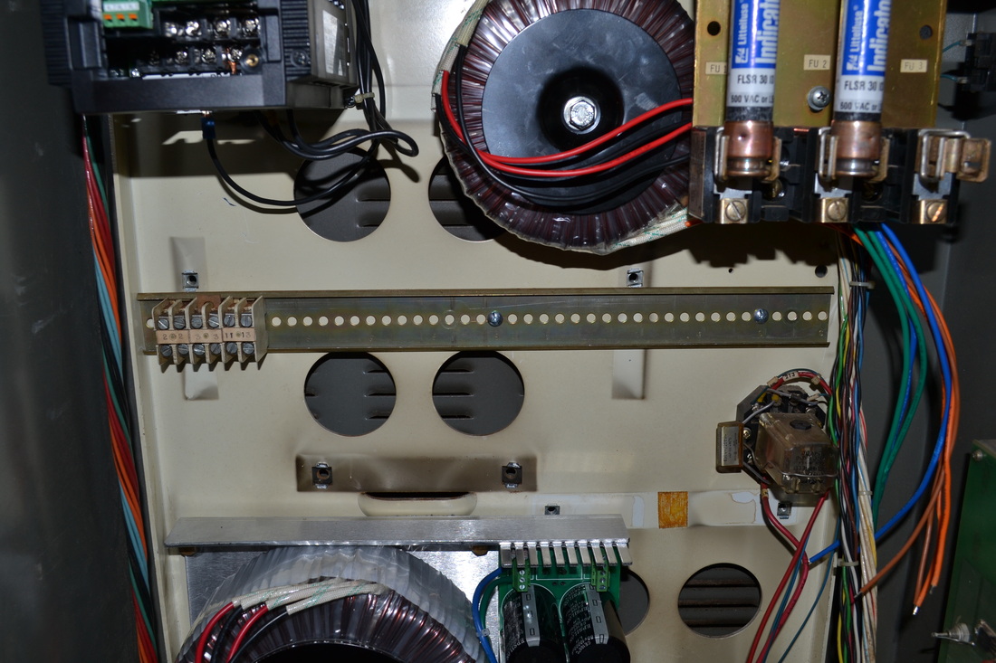
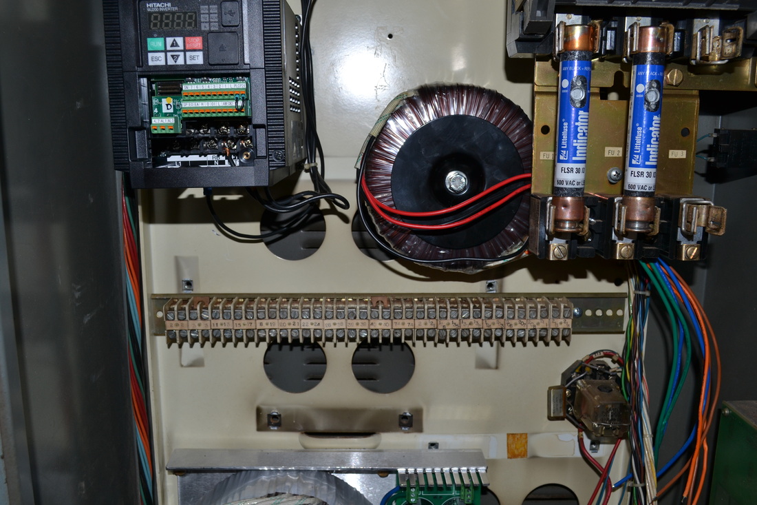
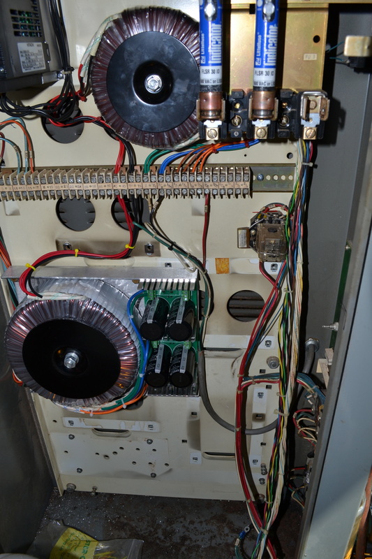
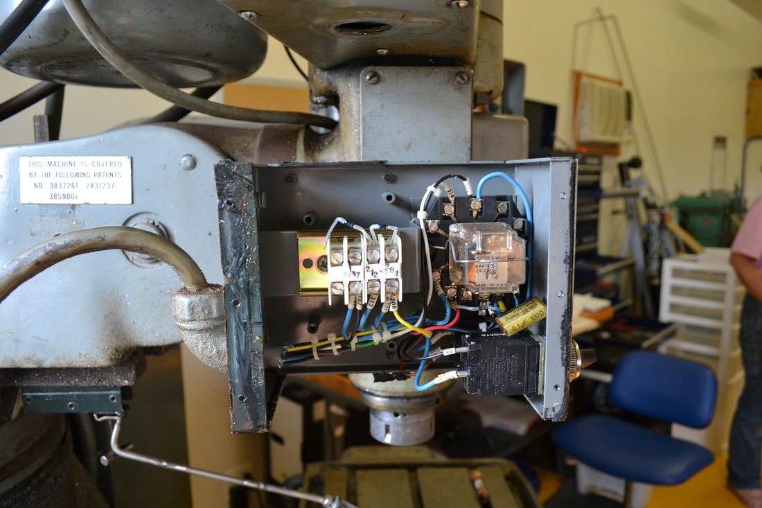
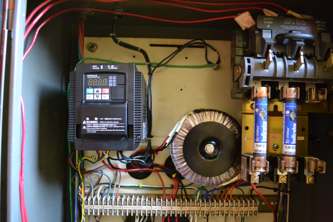
I got really lucky. The 7/16" Hex head bolts are 1/4-20's and SX1 and SX3's top right holes are 7" apart, matching the Antek 1500W power supply. I can get 2 bolts into the original holes, with nut inserts already present. If the power supply is put sideways as shown, then a securing hole for a zip tie also matches a third hole, and the fourth can easily be drilled. Two 1/4-20 nuts can be used to secure this in place. The only problem is that the primary wires are about 3" too short to make it to the disconnect switch. No matter, I'll just install a terminal strip. This can help me collect all my 240V wiring, anyway. Cleaner and tidier.
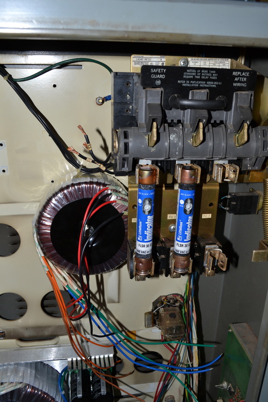
Now to find a mounting hole for the 240 to 120V stepdown transformer. It looks like the top right hole for T2 will work just fine, but the thread for the supplied mounting bolt must be metric.
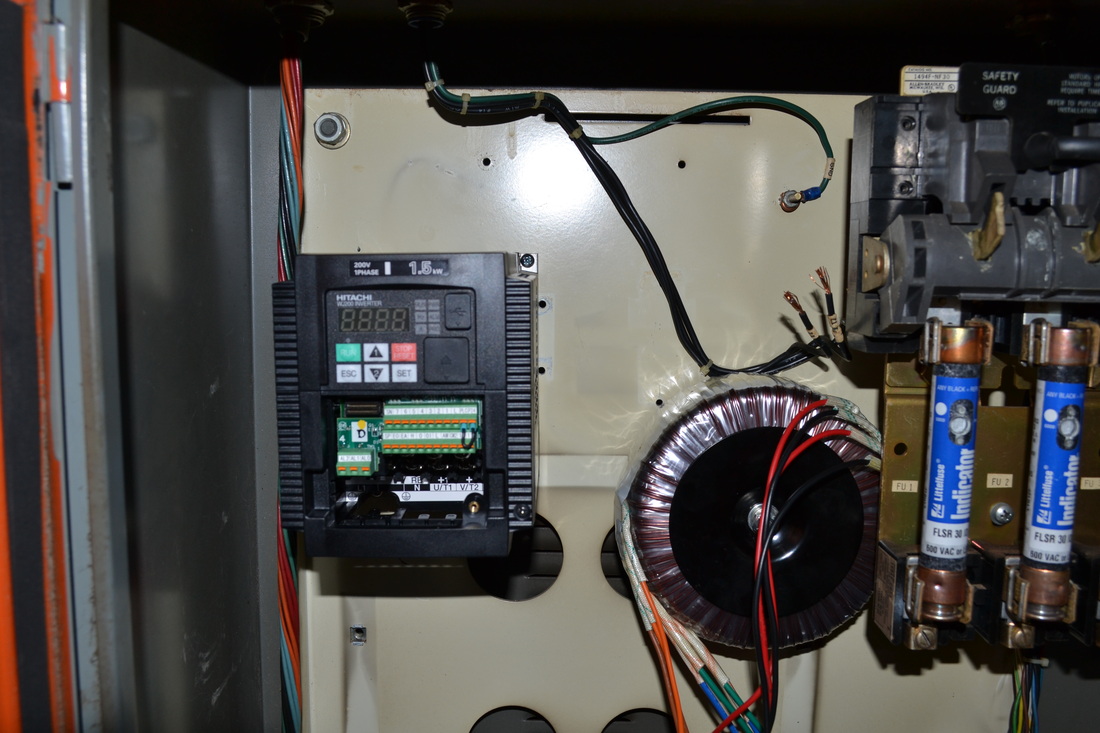
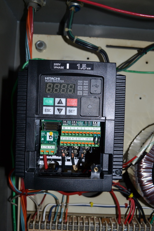
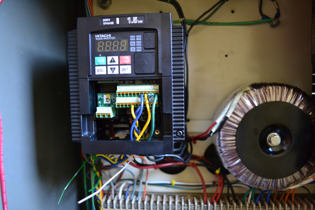
VFD arrived during lunch! Ran to the hardware store. Need to get fasteners for the VFD and I will need to drill new holes for it. I can tap the holes in the back plate and we'll be all set. I also need two 1/4-20 nuts (because I don't have them on hand) and a 5/16-18x3.5" bolt for the step down transformer. The transformer comes supplied with an M8, but I have a 5/16-18 nut insert I can use to mount it (another remnant of the T2 mounting hardware). It looks like I'm in good shape. I'll also need some wire and the terminal strip. I know I have a terminal strip somewhere, but finding it? Who knows.
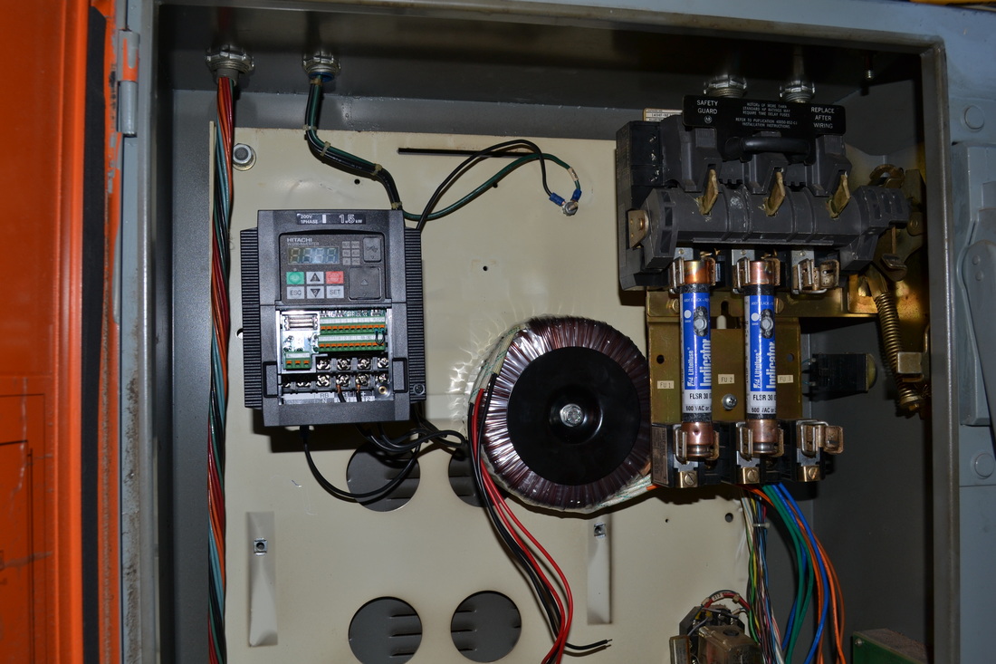
Mounted the transformer and the power supply. #8-32 hardware works instead of the M4 hardware that was specified for the Hitachi drive, but I'll need to drill and tap the holes. None line up. I need to get the tap, so this is put off to tomorrow.
VFD is now wired to the motor and to ground. I can't help but get excited at this small step toward reassembly!
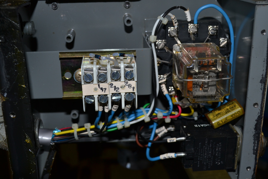
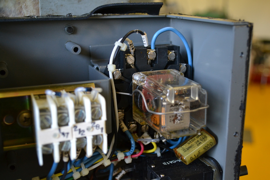
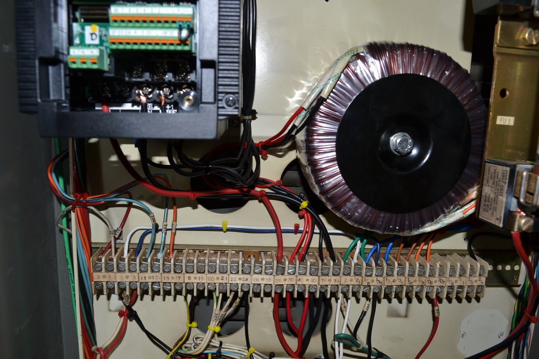
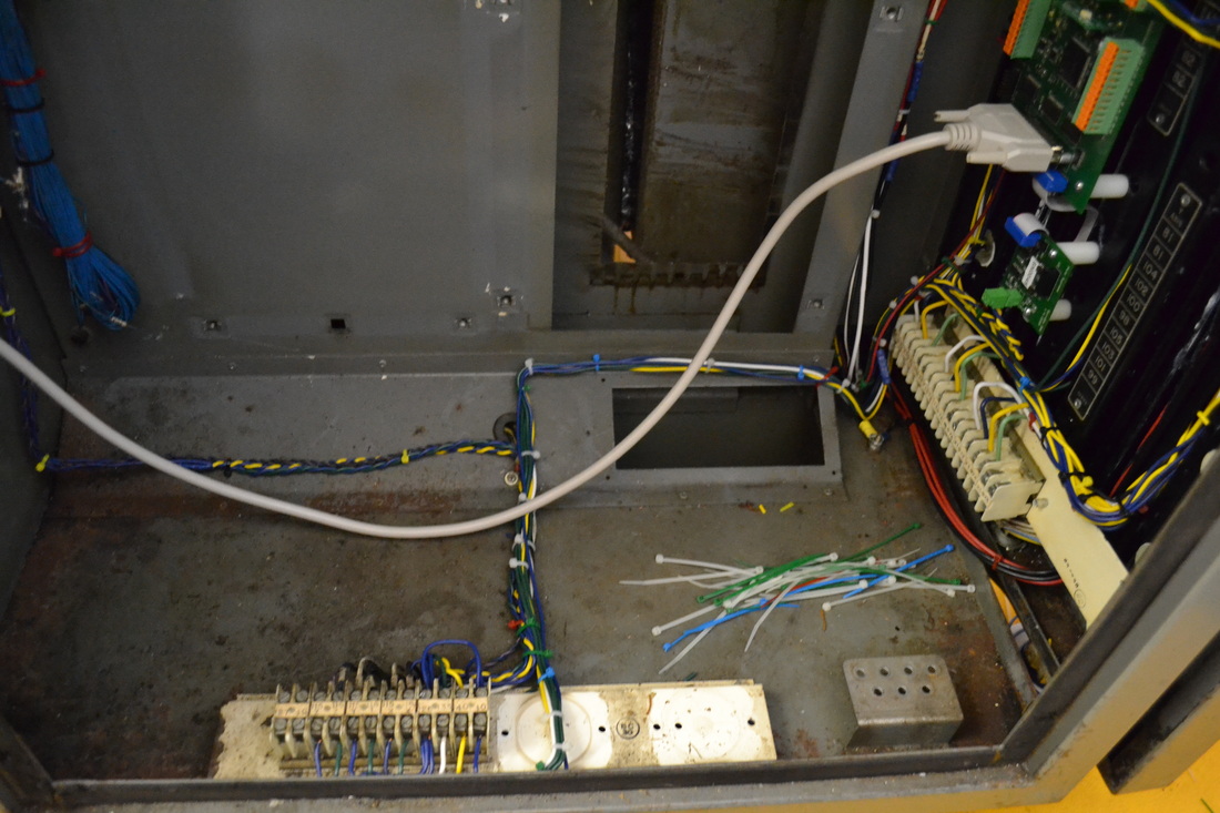
Now mount the DIN rail from the power cabinet terminal strip. It's just the ticket for all of our terminal strip needs, and it's free! First remove all the terminals by pressing on the brass tab at the top or bottom, then gently angle it out. I have to finish removing the wires from it before I separate it. Then unscrew the rail from the bracket, and drill and tap holes in the back plate, then fasten it!
I left space on either end so that I would have room for cable routing.
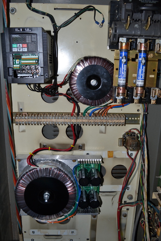
Reusing the bus-bars from the old control, I wired up the two transformers' primary wiring, leaving room for the VFD and power in when I get suitable wire. For those two, use 10 gauge wiring to ensure adequate current capacity. Though the VFD should only draw ~17 amps max, it doesn't hurt to have to 10 AWG wire. The wires from the fuses to the terminal strip should be 10AWG so that they are not overloaded, as the total draw of the machine runs through these two wires.
Tidy up the wiring as it sits.
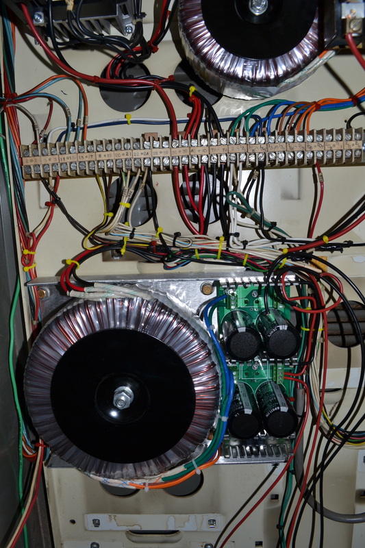
Wire the Common terminals on the stepper power supply to ground.
It wouldn't hurt to tie the two 70VDC outputs together at this point using a 10 or 12 AWG wire. Do both the "+" and the "-" so that the grounds and voltage outputs are common. When wiring to the Geckos, I'll be pulling off individual wires from the + and - terminals to each stepper motor, but I want to make sure that both sets of windings are used to supply power, rather than loading one more heavily than the other. This way the difference will be slight.
Refer to the schematic. First I'm going to figure out which wires need to be connected.
In order to connect the emergency stop, connect #214 to EG on Connector P5 of the USC board. This is the emergency stop ground. Then connect #40 to the USC P5, #14 & 15, the E-stop inputs. These wires go to normally closed contacts on the E-Stop connector. Keep in mind that because the E-stop chain is normally closed, all devices triggering an E-Stop MUST be in series. In my case, the only other item I believe will be in this chain is the lube level low alarm, which I may actually give a separate input.
Next, #221 to motor forward input (Normally open) & #230 to USC's EG
Next, #219 to motor reverse input (normally open). This way either 221 or 219 gets pulled low when the motor run switch is turned in the appropriate direction. If neither is commanded from the spindle start panel, the motor will not see +5V DC on both inputs.
Next, the spindle enable pushbutton will not be connected. I believe it's part of the E-Stop chain in the default wiring, but it's a bit of a mess in there and I can't find any reference to it in the schematics. The light would require +24VDC, but I don't feel the need to connect it up at the moment. Perhaps later, there's always time.
At the moment, all the listed connections are documented, but since I haven't wired the control cabinet, they're only going to terminals on the strip, rather than to the USC.
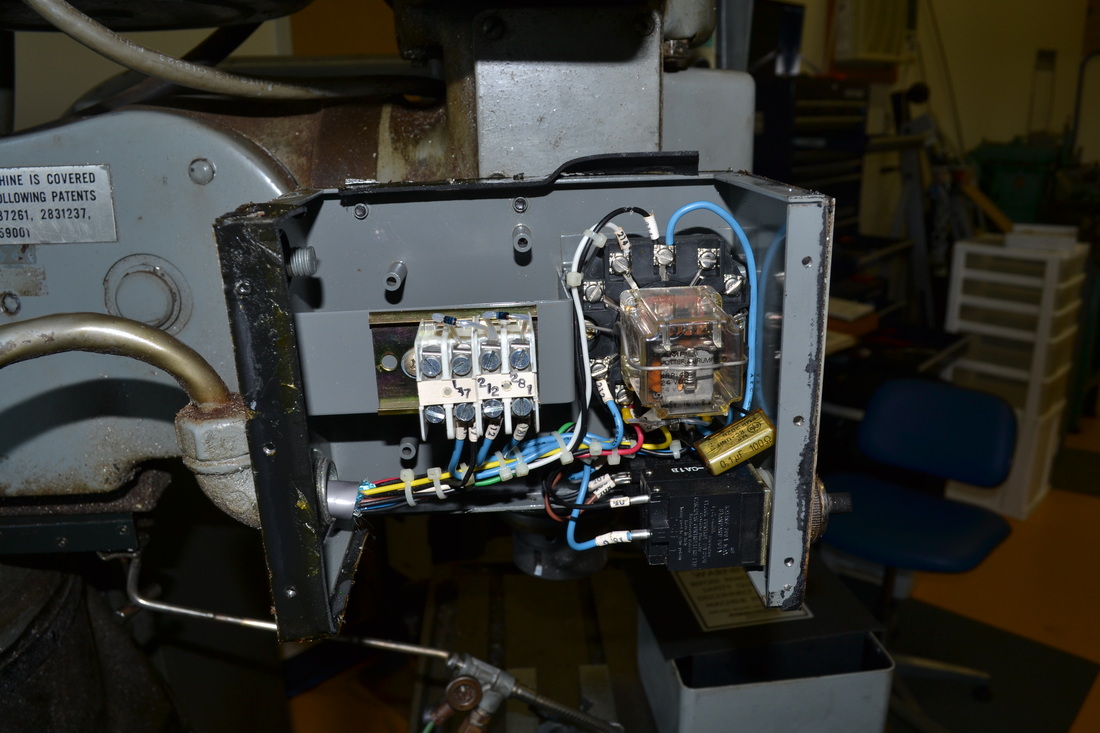
Now on to the lube pump. Wire the white wire, #2, to your 115V neutral. In my case, that's the green wire from the step-down transformer. Wire #121 (black) to 115V, in my case, it's blue from the step-down transformer. Wire #138 (red) is the lube level switch, and it's normally closed with respect to neutral unless the level in the reservoir drops too low. The only problem is that it's common with the neutral. I'll have to investigate further to make sure that it's safe for the USC input. For now I'm giving it a separate terminal strip location, rather than putting it in the E-stop chain.
Next I actually took a step backwards. I undid the wiring to the lube pump motor in order to test the VFD, stepdown transformer, and power supplies. Make sure that you wire the power supply correctly, with the two windings in series rather than parallel, or you'll draw too much current (and not generate the desired voltage). Also make sure that you ohm it out so that you don't connect the red and black of one winding across 240, instead of putting each winding in series. Now we know the VFD and both power supplies are properly connected and the voltage output is as expected for all outputs. NOTE: You can also perform the VFD Powerup test at this time. See below for details, or read the manual (something I didn't do at this point in the process).
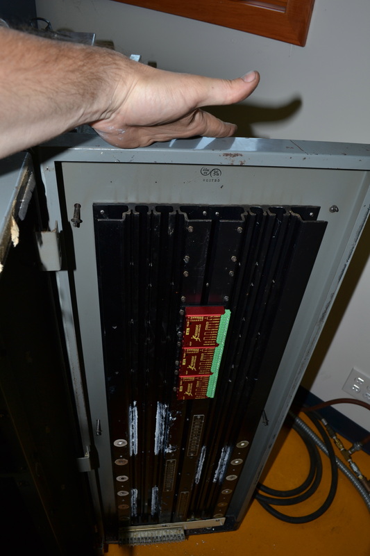
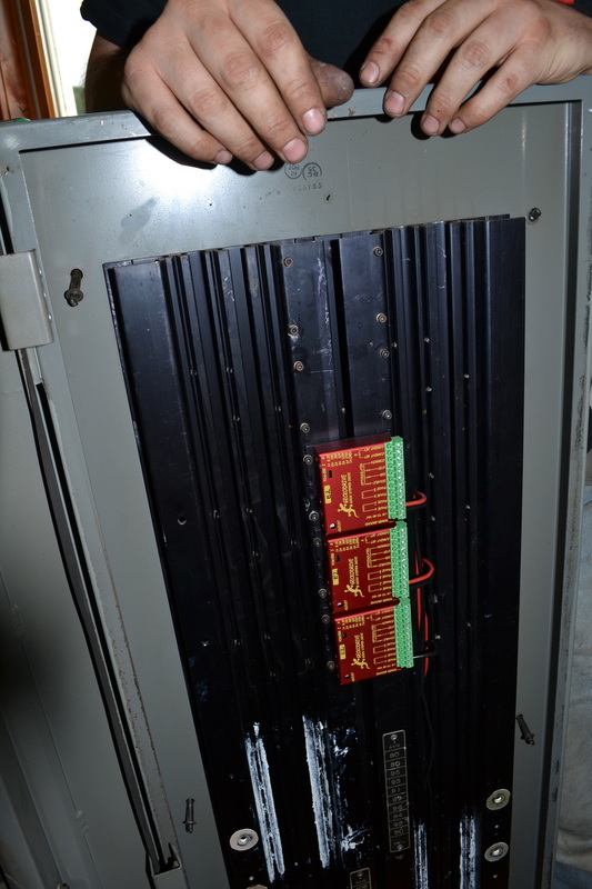
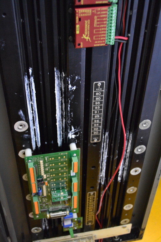
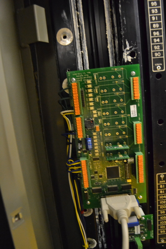
I will now mount the Geckos and the USC board to the heat sink. I'm going to need minimum 6 standoffs, #4-40 Female, #6-32 male, with a standoff height of 1", and some 4-40 screws. Luckily, it's possible for me to use some of the heat sink channels and screw the standoffs right into them, so long as I have sufficient standoff room. The Geckos will need new holes drilled. The spindle DAC board can also use two standoffs and we'll be good to go. Heat sink paste is also required for the Geckos but I know I have some stashed away somewhere.
I'll also need to order through hole fuses for the USC to fuse the SSR's and some SSR's for the various outputs. Mostly, I think I'll need three 24VDC capable relays for the air solenoids. I already ordered the signal level SSRs for the VFD, so that's good to go.
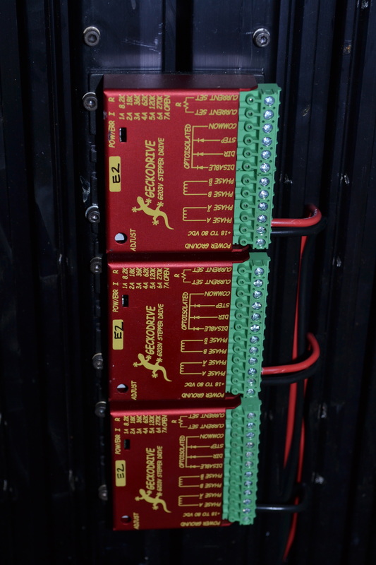
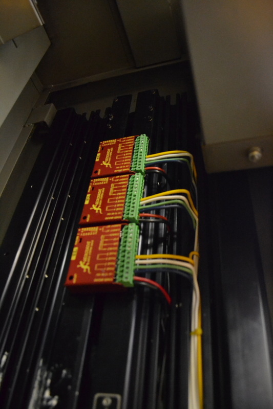
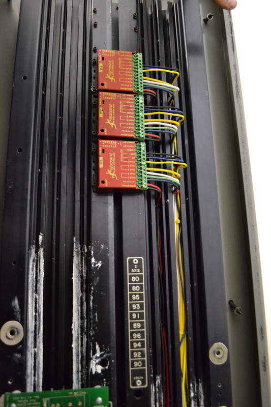
The Geckos are now mounted. Note that I made provisions for two more. Perhaps someday I'll motorize the knee! I have near term plans to convert my 12" rotary table, so I have made it easy on myself for future additions.
Now we need to continue wiring the peripherals. Let's look at the schematics. Lets connect the pneumatic brake & speed adjust controls & solenoids.
Looks like 206 is the spindle brake solenoid (applying +24VDC to the solenoid releases the brake).
207 is the spindle speed increase solenoid (the white w/ yellow striped wire) & the increase switch return is the black wire.
208 is the spindle decrease solenoid (the white one) & the decrease switch return is the red wire.
Wire 137 (black), in the original circuit, supplied 24VDC to the speed switches and the brake solenoid whenever the spindle motor was running. This is no longer going to be the case, so we want to disconnect 137 from the connection at CR5 (in the panel). 137 will now go to EG so that we can detect whenever increase or decrease is pressed on the inputs (208 & 207 from the spindle control panel). The easiest place to disconnect 137 from CR5 is at the terminal block, remove one leg of D59, right above the "137" stamp on the terminal block.
207 & 208 from the solenoids must be wired to two separate SSR's on the USC board. The SSR's will need to supply 24VDC at minimum 1 amp. The fuse should probably also be 1 amp.
206 must also be wired to an SSR on the USC board, as with 207 & 208.
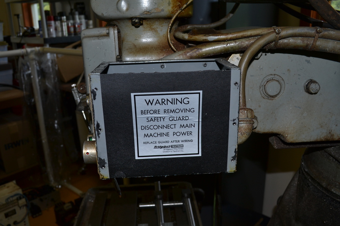
Removing the cover was a bit of a pain, but I got it off. Had to use pliers, as some of the button heads are stripped. I sincerely doubt this has ever been off before, or if it has, the mechanic was careless.
For the brake option, the "auto" switch selects a pin that's not connected. In other words, when the "off" button is selected, the solenoid is powered all the time. When Auto is selected, the solenoid is powered when the motor runs.
In this case, we want to pick off line 40 and connect it to EG on the USC board, and select another wire to route back to the USC as the input. Line 206, the yellow wire from CR5, can be moved from the relay to the terminal strip, connect it to wire 281. You can leave the rest of it. This will be the sensor input for the brake select.
Wire 206, the white w/ green stripe, to the USC board, as discussed above.
Wire 39, common with the solenoids attached to 206, 207, and 208, must be grounded to the 24VDC ground so the solenoids will operate.
The rest of the wires will be taped off and secured out of the way.
Make a list of all the connections that have yet to be made to the USC, etc.
Began pulling wires for the 70VDC supply to the Geckos but ran out of 12 gauge red wire. Yes 12 gauge is overkill, but why not?
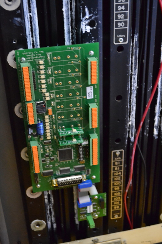
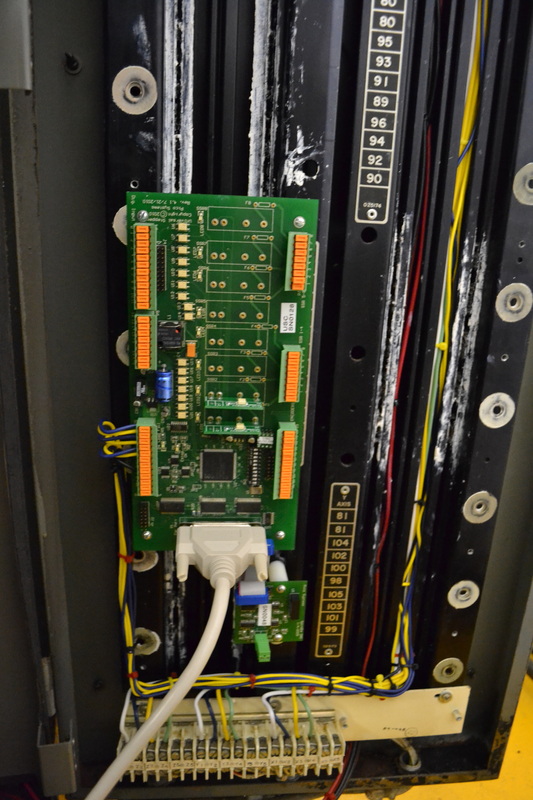
I mounted the usc and spindle DAC with 4-40 screws, 1.5" long, and nylon spacers. This worked very well, but I had to drill new holes. The gaps in the large heatsink are perfect for 6-32 screws, but too large for 4-40's. Luckily, I also bought a tap while at the hardware store.
Finished pulling the 70VDC wires for the Geckos, but I'll wait to bundle them until after I have run everything else through.
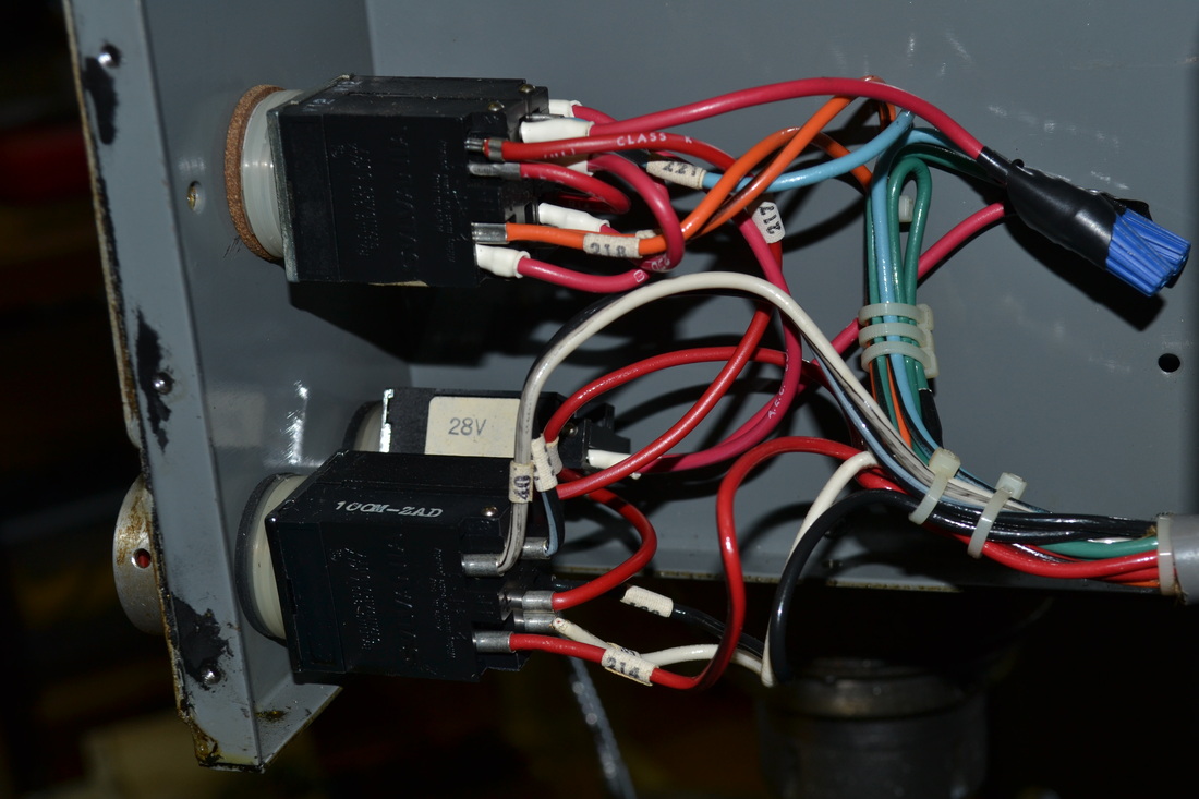
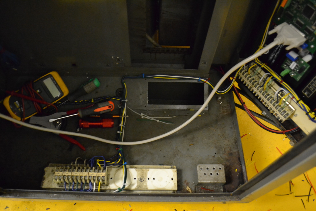
Time to sort out limit switches. Limit wires are marked 115 and 116. Note that the X and Y axis limits come in at the bottom center of the control cabinet, through a grommet. Both cables join up behind that sloped panel, so we'll have to figure out which ones are which. I'll also need that terminal strip off the wiring harness, but I have no need of the relays. Time to strip it down.
Now, judging by the bend in the wires, I've found the X and Y limits, but will test them with a meter. Yep, continuity test checks out for each pair. Now what about Z?
For the Z axis, I see multiple wires coming in. The problem is that they're difficult to discern from the control panel wiring. Pull the Z limit cover with a 5/32 allen wrench. Note that there are two limit switches and a home switch. For all limits, 115 is the common pin and should be connected to EG. 116 should be connected to an input.
For Z, 116 is Z- limit
"Quill Decel" is the switch which, under factory controls, slows the Z once tripped, so it doesn't slam into the Z+ limit. It's wired with "40" and "10."
"Quill Up" is the Z+ limit switch, wired with "40" and "8." Both Quill Decel and Quill Up run to the XDI board, so we'll need to separate the wiring from the bundle.
Assuming you haven't already done so, cut the zip ties from the top down, separating the three pairs of twisted wires. These are the ones we want. The longest two are the Z- limit, and the other two are the decel and up switches. I doubt that we'll use the decel switch, since the machine can be configured to home at a lower search speed, but we might as well wire it to the terminal block. In that case, separate the two 40's where they're wired together, and clip the excess of the other two. Crimp or solder extensions, making sure to twist this as well. Though the X and Y limits are not twisted pairs, it helps to eliminate noise so we might as well continue what was already done. I only have 18 awg on hand, but this will do. I'll crimp some butt splices on, then we'll ohm them out to find which one is which.
As I have it on the terminal strip the "Decel" switch is wired to #40 and is yellow. This will be wired to bit 11 as an extra input, no idea whether I'll use it.
"Up" is going to be the Z+ limit, and is wired to #135 and is green.
Now that all the limit switches are wired to the lower terminal strip, we can take a look at the stepper motor wiring. Finally, the last of the peripheral devices. The wiring hasn't been touched from the heat sink terminal strip, so it's exactly as it was before we started messing around.
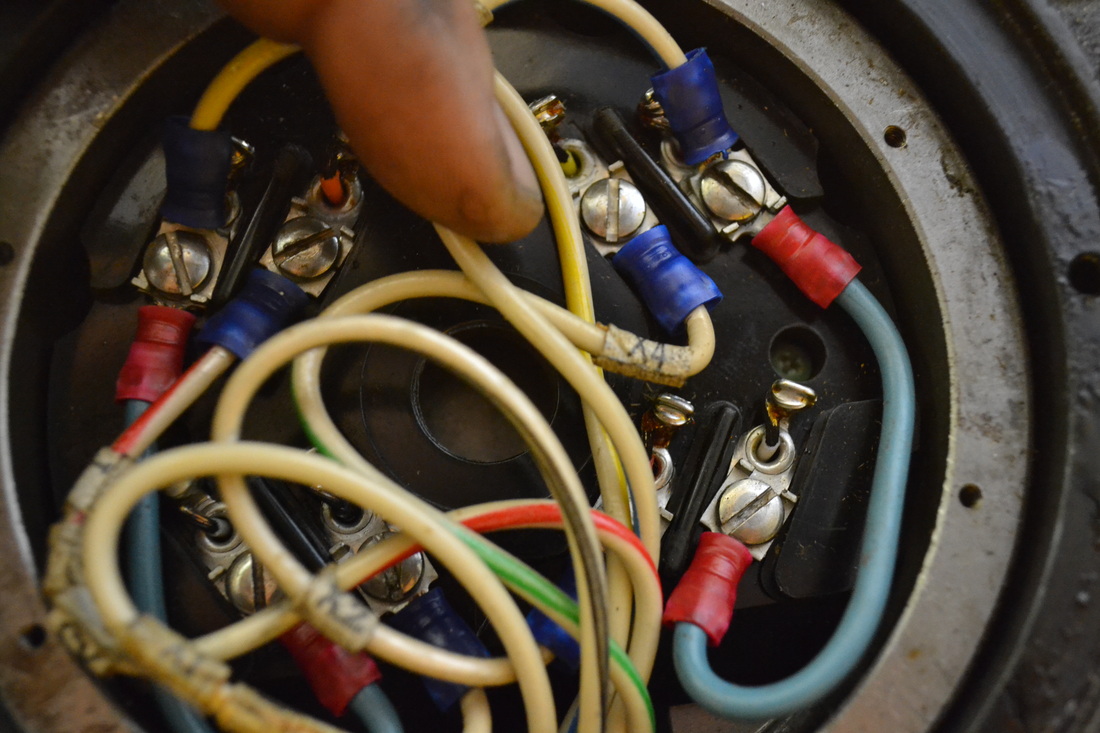
Let's see ... So it looks like the Z and X axis motors are Sigma motors. We're going to wire the windings in series, so:
6 is jumpered to 5
3 goes to A
1 goes to /A
8 is jumpered to 7
4 goes to B
2 goes to /B
Let's do the X axis rewiring first, then finish up the other connections necessary to make it run. Then we can verify it works before we make more changes.
So far 5 is already connected to 6, and the wire X5 (white w/ blue stripe) is connected to it - not to be used
Terminal 3 has X2 attached (white & black stripe), so it's ok.
Terminal 1 has X4 attached (white w/ green), so it's ok.
8 is already jumpered to 7, w/ X5 (white w/ yellow), so it's ok - X5 won't be used.
Terminal 4 has X1 attached (white), so it's ok.
Terminal 2 has X3 attached (white w/ red), so it's ok.
Looks like we don't need to do any rewiring! What a treat!
OK, now we need to make the connections in from the terminal strip to the gecko driver (and verify wire colors). Check.
In summary:
X2 to A
X4 to /A
X1 to B
X3 to /B
I took a chance and wired Y and Z, assuming that they're also already wired in series. If that doesn't work, we'll know soon enough. NOTE: Yes, they are already wired in series. No need to rewire the motors!
Why do we want series instead of parallel, you may ask. Because, frankly, if the motors are wired in series, you could supply a maximum of 8 amps, but in parallel, you could supply up to 16 amps. Since the Gecko drivers will only supply 7, it serves no purpose to wire in parallel, as the drivers would not supply anywhere near the motor's current capacity. Why do we care? Because low speed operation is determined by the current limit, and high speed operation is determined by the voltage limit. Upping the voltage from 56V to 70V improves our high speed performance over previous, and maintaining series wiring maintains our low speed performance. Should we go to parallel, we would see a substantial drop in low speed torque unless we used much higher current drivers. For more on all of this, see the Gecko step motor basics guide. It's very informative!
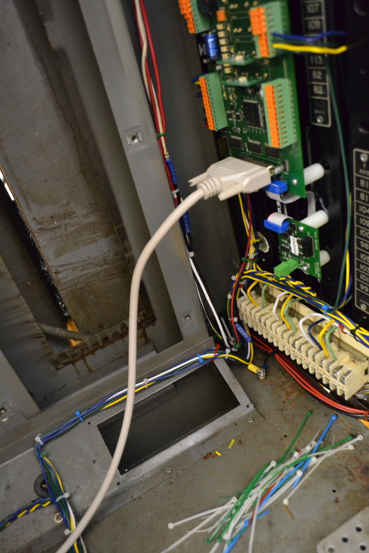
Why don't we attach the parallel port cable? I removed the old serial port panel and ran the cable through the hole. Not pretty, but it'll do for now. In the future I'll mount a panel and get a second cable to connect to, but in the meantime, this lets us test everything once it's wired up. I may also fit the computer inside the cabinet. There's PLENTY of room for it! Trouble is then I'd need longer keyboard, mouse, and monitor cables ... ahh the fun of retrofitting!
Now on to wiring the USC to Gecko connection. That's a good start, then we'll continue wiring the rest of the USC, connecting up limits and the other peripherals. Inputs first, then outputs.
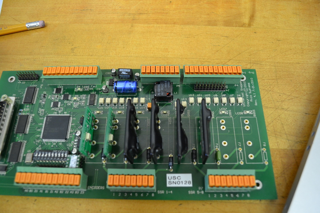
Looking at the G203V manual, revision 7, I see that terminal 8 is direction, terminal 9 is step, and terminal 10 is logic ground. The gecko schematic for the USC seems to have an error, at least according to the G203V manual. For now, I'm going to connect the step ground from the USC's P2, pin 9 to each of the drivers' terminal 10. Because I'm using the punchdown terminals on the board, I'm not crazy about trying to put multiple grounds in there, so I'll daisy chain them off the geckos instead. Not great either way, but it'd probably be less noisy to run the grounds back to the USC.
Wired the step and direction inputs, with S0/D0 as X, S1/D1 as Y, and S2/D2 as Z.
Geckos are done, as I don't need a current limiting resistor and won't be connecting the disable pin.
Let's wire the limit switches to the USC.
First let's gather all the EG pins together. These are then run to a spare terminal space, and the EG wires from the power cabinet will be collected here. A wire is then run to the EG terminal on the USC.
Bit 0: (X home) N/C
Bit 1: (-X Limit) The X limit will be wired to -X
Bit 2: (+X limit) N/C
Bit 3: (available) Planned Spindle Speed Input -> Will Use 4th Axis Encoder Inputs
Bit 4: (Y Home) N/C
Bit 5: (-Y Limit) The Y limit is wired to -Y
Bit 6: (+Y Limit) Lube Level
Bit 7: (available) Speed Increase
Bit 8: (Z Home) Speed Decrease
Bit 9: (-Z Limit) This is wired to the Z limit
Bit 10: (+Z Limit) This is wired to "Quill Up"
Bit 11: (available) This is wired to "Quill Decel"
Bit 12: (available) Spindle Brake
Bit 13: (available) Spindle Rev
Bit 14: (available) Spindle Fwd
Bit 15: (E-Stop OK) This is wired to the E-stop button
EG: (Input Ground) Misc input grounds (lube level, spindle dir input gnds, speed/brake input gnds - #40, 40, 137@2, 230@11, #2@2)
E+5: (Isolated +5V Source) N/C
The limits are all wired, but I have a few of the others to do yet.
Also need to connect:
+12V to SSR1 Pwr Input --DONE
SSR1 Output to VFD Pin1 --DONE
+12V to SSR2 Pwr Input --DONE
SSR2 Output to VFD Pin2 --DONE
VFD ground to +12V ground --DONE
+24V to SSR3, 4, and 5 Pwr Input
SSR3 Output to 206 (spindle brake)
SSR4 Output to 207 (speed incr.)
SSR5 Output to 208 (speed decr.)
+120V to SSR6 Pwr Input
SSR6 Output to Unmarked Black wire @ 214 (coolant on)
Finish wiring +70VDC to Geckos
Ground cabinet chassis together
Connect Solenoid ground to 24V Ground --DONE
Make sure coolant ground is connected. ??
VFD Analog Output & ground from DAC board
+12V & Ground to USC board
Think that's it!
Ok, Gecko power supplies are fully connected. In addition, the 12 and 24V power supplies are grounded to the chassis and the control cabinet is electrically connected to the power cabinet. This way we can pull DC ground from either grounding terminal. This is common with the mains ground, but isolated from "EG."
I've been reading the VFD manual, there's a powerup test that is recommended before any control wiring is connected. Let's do that now.
The powerup test checks out and I've begun messing with some of the parameters.
I managed to overload the spindle on decel by setting the decel time too short. I corrected the decel parameter back to 10 seconds, so it shouldn't trip, no matter what happens. I need to get the spindle brake up and running and this issue should be moot. Alternately, I can simply figure out how to get the spindle to coast rather than decel. I don't need to apply power to it with the spindle brake engaged. Something to investigate. NOTE: Turns out that you HAVE to set the VFD to coast on Decel or it'll trip an error code when the brake engages. More on this later.
To-Do's for Wiring of the VFD:
Twisted pair of wires should run from the spindle DAC board V & Gnd to the "0" and "L" inputs on the bottom row of the terminal strip.
The jumper should be switched from "PLC to P24" to instead go between "PLC" and "L".
The "P24" connection should then be made to SSR1 & 2 power in.
SSR1 Output should be run to "1" on the VFD
SSR2 Output should be run to "2" on the VFD
Need to reset A001 parameter to external analog input control -- Didn't do this yet.
Need to calibrate speed range on LinuxCNC & Set max speed parameter in VFD -- Didn't do this as of writing because I'm using the air motors to control spindle speed.
Wired the P24 connection to a terminal strip point, then took two wires back to SSR1 source and SSR2 source.
Now wiring the SSR outputs.
Wired up the +12V to the USC board and the ground.
Wired the control cabinet 120V fans, so these are good to go.
I'm wiring the E-Stop then we should be good to test the USC and begin testing things out. The VFD control won't work because the fuses are not installed on the SSR's. They're in the mail, so I hope to get them tomorrow.
Now to find a mounting hole for the 240 to 120V stepdown transformer. It looks like the top right hole for T2 will work just fine, but the thread for the supplied mounting bolt must be metric.
VFD arrived during lunch! Ran to the hardware store. Need to get fasteners for the VFD and I will need to drill new holes for it. I can tap the holes in the back plate and we'll be all set. I also need two 1/4-20 nuts (because I don't have them on hand) and a 5/16-18x3.5" bolt for the step down transformer. The transformer comes supplied with an M8, but I have a 5/16-18 nut insert I can use to mount it (another remnant of the T2 mounting hardware). It looks like I'm in good shape. I'll also need some wire and the terminal strip. I know I have a terminal strip somewhere, but finding it? Who knows.
Mounted the transformer and the power supply. #8-32 hardware works instead of the M4 hardware that was specified for the Hitachi drive, but I'll need to drill and tap the holes. None line up. I need to get the tap, so this is put off to tomorrow.
VFD is now wired to the motor and to ground. I can't help but get excited at this small step toward reassembly!
Now mount the DIN rail from the power cabinet terminal strip. It's just the ticket for all of our terminal strip needs, and it's free! First remove all the terminals by pressing on the brass tab at the top or bottom, then gently angle it out. I have to finish removing the wires from it before I separate it. Then unscrew the rail from the bracket, and drill and tap holes in the back plate, then fasten it!
I left space on either end so that I would have room for cable routing.
Reusing the bus-bars from the old control, I wired up the two transformers' primary wiring, leaving room for the VFD and power in when I get suitable wire. For those two, use 10 gauge wiring to ensure adequate current capacity. Though the VFD should only draw ~17 amps max, it doesn't hurt to have to 10 AWG wire. The wires from the fuses to the terminal strip should be 10AWG so that they are not overloaded, as the total draw of the machine runs through these two wires.
Tidy up the wiring as it sits.
Wire the Common terminals on the stepper power supply to ground.
It wouldn't hurt to tie the two 70VDC outputs together at this point using a 10 or 12 AWG wire. Do both the "+" and the "-" so that the grounds and voltage outputs are common. When wiring to the Geckos, I'll be pulling off individual wires from the + and - terminals to each stepper motor, but I want to make sure that both sets of windings are used to supply power, rather than loading one more heavily than the other. This way the difference will be slight.
Refer to the schematic. First I'm going to figure out which wires need to be connected.
In order to connect the emergency stop, connect #214 to EG on Connector P5 of the USC board. This is the emergency stop ground. Then connect #40 to the USC P5, #14 & 15, the E-stop inputs. These wires go to normally closed contacts on the E-Stop connector. Keep in mind that because the E-stop chain is normally closed, all devices triggering an E-Stop MUST be in series. In my case, the only other item I believe will be in this chain is the lube level low alarm, which I may actually give a separate input.
Next, #221 to motor forward input (Normally open) & #230 to USC's EG
Next, #219 to motor reverse input (normally open). This way either 221 or 219 gets pulled low when the motor run switch is turned in the appropriate direction. If neither is commanded from the spindle start panel, the motor will not see +5V DC on both inputs.
Next, the spindle enable pushbutton will not be connected. I believe it's part of the E-Stop chain in the default wiring, but it's a bit of a mess in there and I can't find any reference to it in the schematics. The light would require +24VDC, but I don't feel the need to connect it up at the moment. Perhaps later, there's always time.
At the moment, all the listed connections are documented, but since I haven't wired the control cabinet, they're only going to terminals on the strip, rather than to the USC.
Now on to the lube pump. Wire the white wire, #2, to your 115V neutral. In my case, that's the green wire from the step-down transformer. Wire #121 (black) to 115V, in my case, it's blue from the step-down transformer. Wire #138 (red) is the lube level switch, and it's normally closed with respect to neutral unless the level in the reservoir drops too low. The only problem is that it's common with the neutral. I'll have to investigate further to make sure that it's safe for the USC input. For now I'm giving it a separate terminal strip location, rather than putting it in the E-stop chain.
Next I actually took a step backwards. I undid the wiring to the lube pump motor in order to test the VFD, stepdown transformer, and power supplies. Make sure that you wire the power supply correctly, with the two windings in series rather than parallel, or you'll draw too much current (and not generate the desired voltage). Also make sure that you ohm it out so that you don't connect the red and black of one winding across 240, instead of putting each winding in series. Now we know the VFD and both power supplies are properly connected and the voltage output is as expected for all outputs. NOTE: You can also perform the VFD Powerup test at this time. See below for details, or read the manual (something I didn't do at this point in the process).
I will now mount the Geckos and the USC board to the heat sink. I'm going to need minimum 6 standoffs, #4-40 Female, #6-32 male, with a standoff height of 1", and some 4-40 screws. Luckily, it's possible for me to use some of the heat sink channels and screw the standoffs right into them, so long as I have sufficient standoff room. The Geckos will need new holes drilled. The spindle DAC board can also use two standoffs and we'll be good to go. Heat sink paste is also required for the Geckos but I know I have some stashed away somewhere.
I'll also need to order through hole fuses for the USC to fuse the SSR's and some SSR's for the various outputs. Mostly, I think I'll need three 24VDC capable relays for the air solenoids. I already ordered the signal level SSRs for the VFD, so that's good to go.
The Geckos are now mounted. Note that I made provisions for two more. Perhaps someday I'll motorize the knee! I have near term plans to convert my 12" rotary table, so I have made it easy on myself for future additions.
Now we need to continue wiring the peripherals. Let's look at the schematics. Lets connect the pneumatic brake & speed adjust controls & solenoids.
Looks like 206 is the spindle brake solenoid (applying +24VDC to the solenoid releases the brake).
207 is the spindle speed increase solenoid (the white w/ yellow striped wire) & the increase switch return is the black wire.
208 is the spindle decrease solenoid (the white one) & the decrease switch return is the red wire.
Wire 137 (black), in the original circuit, supplied 24VDC to the speed switches and the brake solenoid whenever the spindle motor was running. This is no longer going to be the case, so we want to disconnect 137 from the connection at CR5 (in the panel). 137 will now go to EG so that we can detect whenever increase or decrease is pressed on the inputs (208 & 207 from the spindle control panel). The easiest place to disconnect 137 from CR5 is at the terminal block, remove one leg of D59, right above the "137" stamp on the terminal block.
207 & 208 from the solenoids must be wired to two separate SSR's on the USC board. The SSR's will need to supply 24VDC at minimum 1 amp. The fuse should probably also be 1 amp.
206 must also be wired to an SSR on the USC board, as with 207 & 208.
Removing the cover was a bit of a pain, but I got it off. Had to use pliers, as some of the button heads are stripped. I sincerely doubt this has ever been off before, or if it has, the mechanic was careless.
For the brake option, the "auto" switch selects a pin that's not connected. In other words, when the "off" button is selected, the solenoid is powered all the time. When Auto is selected, the solenoid is powered when the motor runs.
In this case, we want to pick off line 40 and connect it to EG on the USC board, and select another wire to route back to the USC as the input. Line 206, the yellow wire from CR5, can be moved from the relay to the terminal strip, connect it to wire 281. You can leave the rest of it. This will be the sensor input for the brake select.
Wire 206, the white w/ green stripe, to the USC board, as discussed above.
Wire 39, common with the solenoids attached to 206, 207, and 208, must be grounded to the 24VDC ground so the solenoids will operate.
The rest of the wires will be taped off and secured out of the way.
Make a list of all the connections that have yet to be made to the USC, etc.
Began pulling wires for the 70VDC supply to the Geckos but ran out of 12 gauge red wire. Yes 12 gauge is overkill, but why not?
I mounted the usc and spindle DAC with 4-40 screws, 1.5" long, and nylon spacers. This worked very well, but I had to drill new holes. The gaps in the large heatsink are perfect for 6-32 screws, but too large for 4-40's. Luckily, I also bought a tap while at the hardware store.
Finished pulling the 70VDC wires for the Geckos, but I'll wait to bundle them until after I have run everything else through.
Time to sort out limit switches. Limit wires are marked 115 and 116. Note that the X and Y axis limits come in at the bottom center of the control cabinet, through a grommet. Both cables join up behind that sloped panel, so we'll have to figure out which ones are which. I'll also need that terminal strip off the wiring harness, but I have no need of the relays. Time to strip it down.
Now, judging by the bend in the wires, I've found the X and Y limits, but will test them with a meter. Yep, continuity test checks out for each pair. Now what about Z?
For the Z axis, I see multiple wires coming in. The problem is that they're difficult to discern from the control panel wiring. Pull the Z limit cover with a 5/32 allen wrench. Note that there are two limit switches and a home switch. For all limits, 115 is the common pin and should be connected to EG. 116 should be connected to an input.
For Z, 116 is Z- limit
"Quill Decel" is the switch which, under factory controls, slows the Z once tripped, so it doesn't slam into the Z+ limit. It's wired with "40" and "10."
"Quill Up" is the Z+ limit switch, wired with "40" and "8." Both Quill Decel and Quill Up run to the XDI board, so we'll need to separate the wiring from the bundle.
Assuming you haven't already done so, cut the zip ties from the top down, separating the three pairs of twisted wires. These are the ones we want. The longest two are the Z- limit, and the other two are the decel and up switches. I doubt that we'll use the decel switch, since the machine can be configured to home at a lower search speed, but we might as well wire it to the terminal block. In that case, separate the two 40's where they're wired together, and clip the excess of the other two. Crimp or solder extensions, making sure to twist this as well. Though the X and Y limits are not twisted pairs, it helps to eliminate noise so we might as well continue what was already done. I only have 18 awg on hand, but this will do. I'll crimp some butt splices on, then we'll ohm them out to find which one is which.
As I have it on the terminal strip the "Decel" switch is wired to #40 and is yellow. This will be wired to bit 11 as an extra input, no idea whether I'll use it.
"Up" is going to be the Z+ limit, and is wired to #135 and is green.
Now that all the limit switches are wired to the lower terminal strip, we can take a look at the stepper motor wiring. Finally, the last of the peripheral devices. The wiring hasn't been touched from the heat sink terminal strip, so it's exactly as it was before we started messing around.
Let's see ... So it looks like the Z and X axis motors are Sigma motors. We're going to wire the windings in series, so:
6 is jumpered to 5
3 goes to A
1 goes to /A
8 is jumpered to 7
4 goes to B
2 goes to /B
Let's do the X axis rewiring first, then finish up the other connections necessary to make it run. Then we can verify it works before we make more changes.
So far 5 is already connected to 6, and the wire X5 (white w/ blue stripe) is connected to it - not to be used
Terminal 3 has X2 attached (white & black stripe), so it's ok.
Terminal 1 has X4 attached (white w/ green), so it's ok.
8 is already jumpered to 7, w/ X5 (white w/ yellow), so it's ok - X5 won't be used.
Terminal 4 has X1 attached (white), so it's ok.
Terminal 2 has X3 attached (white w/ red), so it's ok.
Looks like we don't need to do any rewiring! What a treat!
OK, now we need to make the connections in from the terminal strip to the gecko driver (and verify wire colors). Check.
In summary:
X2 to A
X4 to /A
X1 to B
X3 to /B
I took a chance and wired Y and Z, assuming that they're also already wired in series. If that doesn't work, we'll know soon enough. NOTE: Yes, they are already wired in series. No need to rewire the motors!
Why do we want series instead of parallel, you may ask. Because, frankly, if the motors are wired in series, you could supply a maximum of 8 amps, but in parallel, you could supply up to 16 amps. Since the Gecko drivers will only supply 7, it serves no purpose to wire in parallel, as the drivers would not supply anywhere near the motor's current capacity. Why do we care? Because low speed operation is determined by the current limit, and high speed operation is determined by the voltage limit. Upping the voltage from 56V to 70V improves our high speed performance over previous, and maintaining series wiring maintains our low speed performance. Should we go to parallel, we would see a substantial drop in low speed torque unless we used much higher current drivers. For more on all of this, see the Gecko step motor basics guide. It's very informative!
Why don't we attach the parallel port cable? I removed the old serial port panel and ran the cable through the hole. Not pretty, but it'll do for now. In the future I'll mount a panel and get a second cable to connect to, but in the meantime, this lets us test everything once it's wired up. I may also fit the computer inside the cabinet. There's PLENTY of room for it! Trouble is then I'd need longer keyboard, mouse, and monitor cables ... ahh the fun of retrofitting!
Now on to wiring the USC to Gecko connection. That's a good start, then we'll continue wiring the rest of the USC, connecting up limits and the other peripherals. Inputs first, then outputs.
Looking at the G203V manual, revision 7, I see that terminal 8 is direction, terminal 9 is step, and terminal 10 is logic ground. The gecko schematic for the USC seems to have an error, at least according to the G203V manual. For now, I'm going to connect the step ground from the USC's P2, pin 9 to each of the drivers' terminal 10. Because I'm using the punchdown terminals on the board, I'm not crazy about trying to put multiple grounds in there, so I'll daisy chain them off the geckos instead. Not great either way, but it'd probably be less noisy to run the grounds back to the USC.
Wired the step and direction inputs, with S0/D0 as X, S1/D1 as Y, and S2/D2 as Z.
Geckos are done, as I don't need a current limiting resistor and won't be connecting the disable pin.
Let's wire the limit switches to the USC.
First let's gather all the EG pins together. These are then run to a spare terminal space, and the EG wires from the power cabinet will be collected here. A wire is then run to the EG terminal on the USC.
Bit 0: (X home) N/C
Bit 1: (-X Limit) The X limit will be wired to -X
Bit 2: (+X limit) N/C
Bit 3: (available) Planned Spindle Speed Input -> Will Use 4th Axis Encoder Inputs
Bit 4: (Y Home) N/C
Bit 5: (-Y Limit) The Y limit is wired to -Y
Bit 6: (+Y Limit) Lube Level
Bit 7: (available) Speed Increase
Bit 8: (Z Home) Speed Decrease
Bit 9: (-Z Limit) This is wired to the Z limit
Bit 10: (+Z Limit) This is wired to "Quill Up"
Bit 11: (available) This is wired to "Quill Decel"
Bit 12: (available) Spindle Brake
Bit 13: (available) Spindle Rev
Bit 14: (available) Spindle Fwd
Bit 15: (E-Stop OK) This is wired to the E-stop button
EG: (Input Ground) Misc input grounds (lube level, spindle dir input gnds, speed/brake input gnds - #40, 40, 137@2, 230@11, #2@2)
E+5: (Isolated +5V Source) N/C
The limits are all wired, but I have a few of the others to do yet.
Also need to connect:
+12V to SSR1 Pwr Input --DONE
SSR1 Output to VFD Pin1 --DONE
+12V to SSR2 Pwr Input --DONE
SSR2 Output to VFD Pin2 --DONE
VFD ground to +12V ground --DONE
+24V to SSR3, 4, and 5 Pwr Input
SSR3 Output to 206 (spindle brake)
SSR4 Output to 207 (speed incr.)
SSR5 Output to 208 (speed decr.)
+120V to SSR6 Pwr Input
SSR6 Output to Unmarked Black wire @ 214 (coolant on)
Finish wiring +70VDC to Geckos
Ground cabinet chassis together
Connect Solenoid ground to 24V Ground --DONE
Make sure coolant ground is connected. ??
VFD Analog Output & ground from DAC board
+12V & Ground to USC board
Think that's it!
Ok, Gecko power supplies are fully connected. In addition, the 12 and 24V power supplies are grounded to the chassis and the control cabinet is electrically connected to the power cabinet. This way we can pull DC ground from either grounding terminal. This is common with the mains ground, but isolated from "EG."
I've been reading the VFD manual, there's a powerup test that is recommended before any control wiring is connected. Let's do that now.
The powerup test checks out and I've begun messing with some of the parameters.
I managed to overload the spindle on decel by setting the decel time too short. I corrected the decel parameter back to 10 seconds, so it shouldn't trip, no matter what happens. I need to get the spindle brake up and running and this issue should be moot. Alternately, I can simply figure out how to get the spindle to coast rather than decel. I don't need to apply power to it with the spindle brake engaged. Something to investigate. NOTE: Turns out that you HAVE to set the VFD to coast on Decel or it'll trip an error code when the brake engages. More on this later.
To-Do's for Wiring of the VFD:
Twisted pair of wires should run from the spindle DAC board V & Gnd to the "0" and "L" inputs on the bottom row of the terminal strip.
The jumper should be switched from "PLC to P24" to instead go between "PLC" and "L".
The "P24" connection should then be made to SSR1 & 2 power in.
SSR1 Output should be run to "1" on the VFD
SSR2 Output should be run to "2" on the VFD
Need to reset A001 parameter to external analog input control -- Didn't do this yet.
Need to calibrate speed range on LinuxCNC & Set max speed parameter in VFD -- Didn't do this as of writing because I'm using the air motors to control spindle speed.
Wired the P24 connection to a terminal strip point, then took two wires back to SSR1 source and SSR2 source.
Now wiring the SSR outputs.
Wired up the +12V to the USC board and the ground.
Wired the control cabinet 120V fans, so these are good to go.
I'm wiring the E-Stop then we should be good to test the USC and begin testing things out. The VFD control won't work because the fuses are not installed on the SSR's. They're in the mail, so I hope to get them tomorrow.


 RSS Feed
