Why would I want a spindle encoder, you might ask. After all, Bridgeport CNC mills of this type didn't have it through the 90's. The Interact mills, which are essentially the same machine with updated controls, still did not have spindle encoders. Why would you want one in any case, you may wonder. Why indeed! My standard answer to questions like these goes something like "why wouldn't you want X?" But this doesn't really answer the question, does it?
Ever want to do rigid tapping? Oh yes, the ability to mount a tap in a collet and power tap perfect threaded holes without a need for tapping arms, special setups, etc, etc. All done in CNC. A true marvel of modern technology. Sounds wonderful, doesn't it?
Ever think about how you might more fully automate the machine? What if your machine is in backgear and you load a tool that should be run in high gear? How do you automatically detect if the spindle is turning the right direction and adjust speed without any human intervention? A spindle encoder, of course! Though the coding to achieve this feat isn't trivial, it can be done thanks to LinuxCNC and a suitable spindle encoder!
Fitting a Stub Spindle for the Encoder Wheel
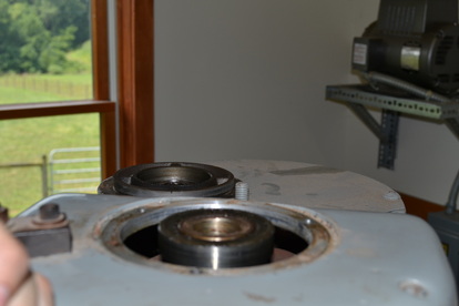
I measured the bore in the top of the spindle for fitting an encoder. It measures 1.031" with my caliper. Though the caliper usually shows a little small with bores, that's in the neighborhood of what I can get away with using a keyless shaft bushing (i.e. trantorque brand). I plan to order one, along with a matching encoder. I will then only need to fab a plate for mounting the encoder body to the head. Luckily, the upper spindle bearing plate has 3 unused tapped holes (1/4-20). I just have to see if I can find a print, or make one myself. It would be good to use larger clearance holes so that I can shift the plate a bit to help align the encoder body to the encoder disc.
Ordered the encoder and bushing. The shaft bushing *should* be able to accommodate the 0.031" oversize that I need it to handle. We'll see. Then I'd just need to cut a stub of 5/8" drill rod and machine an adapter plate. That'd be a simple job on the mill!
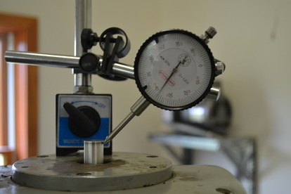
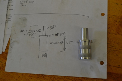
Turns out that the fenner drive bushing wouldn't work because it wouldn't expand the required 1/32" to fill the spindle bore. I shimmed it with some coiled shim stock, but got ~0.015" runout, which is more than the encoder would tolerate. So I took a cue from Igor Chudov's website and made a simple adapter. One end was turned 0.625" and the other turned 1.031. I then knurled the 1.031 end and hammered it into the spindle. It took a bit more force than I would have liked, but it's in. The protruding length is what I wanted, 0.675". I will mount my 0.125" plate with the encoder body on, leaving approximately 0.550, just less than the maximum 0.570" for the encoder. Worst comes to worst, I can shim the encoder body to make it work. But at least it's not shorter than the minimum 0.445" length. Runout turns out to be 0.003" to 0.004" which is just within spec for the encoder. I should have turned the part on the 4-jaw, but it turned out ok. Thank God, because otherwise I would have had a heck of a time getting it out! If I need to remove it in the future, I can always drill and tap the end, then use a gear puller to remove it.
Encoder Body Mounting Plate
Machining the encoder body mount went well until the 4 flute endmill clogged up and spun the work. What a mess. I sawed the part out of the sheet (taped to a piece of 2x12" scrap) and turned it on the lathe to finish it off. Turns out that I also set the OD too small in my program, so it has a bit of a bung where the mill was starting to machine the outside. Overall, it's still fine. Works perfectly. Got the encoder mounted with a quick trip to the hardware store. Now I have to wire it up.
Encoder Wiring
Lets see, referring to the datasheet, I have the pinout, but I didn't bring the cable datasheet so I know which pin corresponds to which wire ... hmm.
Let's look at the USC docs to see where the wires go. Per Jon Elson's instructions, the axis 3 (4th axis) switch should be set to encoder input. Also, on P3 (the encoder input header), Pin 14 is +5V Power, Pin 13 is Ground, Pin 12 is Index3 (I+), Pin 11 is B3 (B+), and Pin 10 is A3 (A+). I chose a US Digital encoder with 512 counts per revolution, quadrature, with Index and differential inputs. The connector pinout is US Digital standard and I used the US Digital cable. The I-, B-, and A- pins should be connected in common with logic ground. I'll twist all 4 wires together and punch them down to the ground terminal. This will minimize the noise that we see on the A+, B+, and I+ pins.
Ok, what pins are what? See below:
Ground -- Green w/ white stripe
I- -- White w/ orange stripe
I+ -- Orange w/ white stripe
A- -- White w/ Blue Stripe
A+ -- Blue w/ white stripe
Power - -- White w/ green stripe
B- -- White w/ brown stripe
B+ -- Brown w/ white stripe.
We should have this connected momentarily. Ok, another problem. Apparently the punchdown connectors do not have GND & 5V Power as I initially thought. Instead they're only brought out on J3, not P3 (the punchdown terminal strips). Reading the documentation again, this is clear, but I just read it completely backwards. I just stripped back enough of the covering to make the wires reach both P2 and P3. I took the ground wires and brought them back to the chassis ground, as there wasn't room for the grounds on P2.
I verified ground on Pin 2 of the connector at the encoder end and +5V on Pin 7 of the encoder end connector. So far so good. Then I plugged it in to the encoder! Let's see what's next.
Configuring LinuxCNC for the Encoder
Let's look at Pico Systems' sample config for the USC threading example.
Opening the .ini file, I see nothing different. Let's check the io.hal file. Nothing pops out. Checking load.hal, I still see nothing different. univstep_motion.hal? Bingo!
There is one line under feedback scaling:
"setp ppmc.0.encoder.03.scale 6912"
The scale value should be set to 2048, which is 4x512. Because it's a quadrature encoder, there are two channels with 512 counts per revolution and they're 90 degrees out of phase. This way we can actually resolve 2048 counts in each revolution. Research quadrature for more information on this subject.
There are also several more lines at the end of the file, beginning with "newsig spindle-index-en bit" I'm still decoding them. It looks like these lines simply enable the spindle index and feed spindle position to motion.spindle-revs. I have to look up motion.spindle-revs to figure out what it is.
I copied the necessary lines over that differ from my config.
Running LinuxCNC, it seems to start fine now that I've added those lines of code. Does it do anything? Not sure yet, have to test!
Testing Rigid Tapping
It has been suggested that I mount a bolt in the spindle, execute a command as if I were tapping the same thread size, and observe (with a finger nail) whether the machine is keeping motion synchronized.
Programming Automatic Spindle Speed Control
This is a project i'm going to defer for the future. It requires a custom component, and a lot of programming work, so for the moment I'll live with the manual speed adjustment. I just have to remember to program the machine to run the right direction for each tool.
Conclusion
See below for my current configuration files. This should work for both spindle encoders and regular converted BOSS machines. The spindle stub was a quick job in the lathe. The mounting plate would have also been easy had I used a 2 flute endmill in aluminum ... lessons learned. Overall, it still came out excellent. And if I get too much time on my hands, I can always add speed feedback! I've included PDF drawings of my spindle stub and encoder mount, but your dimensions may (and probably will) vary. I recommend that you only use these as a guide as I may have made an error (corrected in-process) that I failed to update on the drawing.
I measured the bore in the top of the spindle for fitting an encoder. It measures 1.031" with my caliper. Though the caliper usually shows a little small with bores, that's in the neighborhood of what I can get away with using a keyless shaft bushing (i.e. trantorque brand). I plan to order one, along with a matching encoder. I will then only need to fab a plate for mounting the encoder body to the head. Luckily, the upper spindle bearing plate has 3 unused tapped holes (1/4-20). I just have to see if I can find a print, or make one myself. It would be good to use larger clearance holes so that I can shift the plate a bit to help align the encoder body to the encoder disc.
Ordered the encoder and bushing. The shaft bushing *should* be able to accommodate the 0.031" oversize that I need it to handle. We'll see. Then I'd just need to cut a stub of 5/8" drill rod and machine an adapter plate. That'd be a simple job on the mill!
Turns out that the fenner drive bushing wouldn't work because it wouldn't expand the required 1/32" to fill the spindle bore. I shimmed it with some coiled shim stock, but got ~0.015" runout, which is more than the encoder would tolerate. So I took a cue from Igor Chudov's website and made a simple adapter. One end was turned 0.625" and the other turned 1.031. I then knurled the 1.031 end and hammered it into the spindle. It took a bit more force than I would have liked, but it's in. The protruding length is what I wanted, 0.675". I will mount my 0.125" plate with the encoder body on, leaving approximately 0.550, just less than the maximum 0.570" for the encoder. Worst comes to worst, I can shim the encoder body to make it work. But at least it's not shorter than the minimum 0.445" length. Runout turns out to be 0.003" to 0.004" which is just within spec for the encoder. I should have turned the part on the 4-jaw, but it turned out ok. Thank God, because otherwise I would have had a heck of a time getting it out! If I need to remove it in the future, I can always drill and tap the end, then use a gear puller to remove it.
Encoder Body Mounting Plate
Machining the encoder body mount went well until the 4 flute endmill clogged up and spun the work. What a mess. I sawed the part out of the sheet (taped to a piece of 2x12" scrap) and turned it on the lathe to finish it off. Turns out that I also set the OD too small in my program, so it has a bit of a bung where the mill was starting to machine the outside. Overall, it's still fine. Works perfectly. Got the encoder mounted with a quick trip to the hardware store. Now I have to wire it up.
Encoder Wiring
Lets see, referring to the datasheet, I have the pinout, but I didn't bring the cable datasheet so I know which pin corresponds to which wire ... hmm.
Let's look at the USC docs to see where the wires go. Per Jon Elson's instructions, the axis 3 (4th axis) switch should be set to encoder input. Also, on P3 (the encoder input header), Pin 14 is +5V Power, Pin 13 is Ground, Pin 12 is Index3 (I+), Pin 11 is B3 (B+), and Pin 10 is A3 (A+). I chose a US Digital encoder with 512 counts per revolution, quadrature, with Index and differential inputs. The connector pinout is US Digital standard and I used the US Digital cable. The I-, B-, and A- pins should be connected in common with logic ground. I'll twist all 4 wires together and punch them down to the ground terminal. This will minimize the noise that we see on the A+, B+, and I+ pins.
Ok, what pins are what? See below:
Ground -- Green w/ white stripe
I- -- White w/ orange stripe
I+ -- Orange w/ white stripe
A- -- White w/ Blue Stripe
A+ -- Blue w/ white stripe
Power - -- White w/ green stripe
B- -- White w/ brown stripe
B+ -- Brown w/ white stripe.
We should have this connected momentarily. Ok, another problem. Apparently the punchdown connectors do not have GND & 5V Power as I initially thought. Instead they're only brought out on J3, not P3 (the punchdown terminal strips). Reading the documentation again, this is clear, but I just read it completely backwards. I just stripped back enough of the covering to make the wires reach both P2 and P3. I took the ground wires and brought them back to the chassis ground, as there wasn't room for the grounds on P2.
I verified ground on Pin 2 of the connector at the encoder end and +5V on Pin 7 of the encoder end connector. So far so good. Then I plugged it in to the encoder! Let's see what's next.
Configuring LinuxCNC for the Encoder
Let's look at Pico Systems' sample config for the USC threading example.
Opening the .ini file, I see nothing different. Let's check the io.hal file. Nothing pops out. Checking load.hal, I still see nothing different. univstep_motion.hal? Bingo!
There is one line under feedback scaling:
"setp ppmc.0.encoder.03.scale 6912"
The scale value should be set to 2048, which is 4x512. Because it's a quadrature encoder, there are two channels with 512 counts per revolution and they're 90 degrees out of phase. This way we can actually resolve 2048 counts in each revolution. Research quadrature for more information on this subject.
There are also several more lines at the end of the file, beginning with "newsig spindle-index-en bit" I'm still decoding them. It looks like these lines simply enable the spindle index and feed spindle position to motion.spindle-revs. I have to look up motion.spindle-revs to figure out what it is.
I copied the necessary lines over that differ from my config.
Running LinuxCNC, it seems to start fine now that I've added those lines of code. Does it do anything? Not sure yet, have to test!
Testing Rigid Tapping
It has been suggested that I mount a bolt in the spindle, execute a command as if I were tapping the same thread size, and observe (with a finger nail) whether the machine is keeping motion synchronized.
Programming Automatic Spindle Speed Control
This is a project i'm going to defer for the future. It requires a custom component, and a lot of programming work, so for the moment I'll live with the manual speed adjustment. I just have to remember to program the machine to run the right direction for each tool.
Conclusion
See below for my current configuration files. This should work for both spindle encoders and regular converted BOSS machines. The spindle stub was a quick job in the lathe. The mounting plate would have also been easy had I used a 2 flute endmill in aluminum ... lessons learned. Overall, it still came out excellent. And if I get too much time on my hands, I can always add speed feedback! I've included PDF drawings of my spindle stub and encoder mount, but your dimensions may (and probably will) vary. I recommend that you only use these as a guide as I may have made an error (corrected in-process) that I failed to update on the drawing.
| Click here to upload file |
| encoder_body_mount.pdf |
| spindle_stub.pdf |
 RSS Feed
